Week - 4
OBJECTIVE 1:
To Implement control logic of a “washing machine” using Stateflow as per given sequence:
- If the power supply is available, the system gets activated
- If the Water supply is not available, stop the process & indicate through LED
- Soaking time should be 200s followed by Washing time of 100s.
- Then rinsing happens for next 20s & dryer runs for 50s
After all the processes have completed turn on the finished LED
THEORY:
- A washing machine is a home appliance that is used to wash laundry.
- Modern day washing machines are mostly semi or fully automatic. They used certain control logic to perform different washing processes like soaking, washing, rinsing etc and gives out clean and partially dry clothes.
- Control logic is a key part of a software program that controls the operations of the program. The control logic responds to commands from the user, and it also acts on its own to perform automated tasks that have been structured into the program.
- Control logic can be modeled using a state diagram,which is a form of hierarchical state machine. These state diagrams can also be combined with flow charts to provide a set of computational semantics for describing complex control logic.
MODEL:
LOGIC AND EXPLANATION:
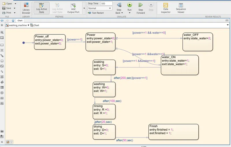
- The first state block is the power block where the power input is not given.
- Then if the power condition is 1(ON), the next state is active where the power state is 1.
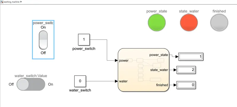
- If the water is 0(OFF),then the washing is stopped and the water LED indicates in RED color.
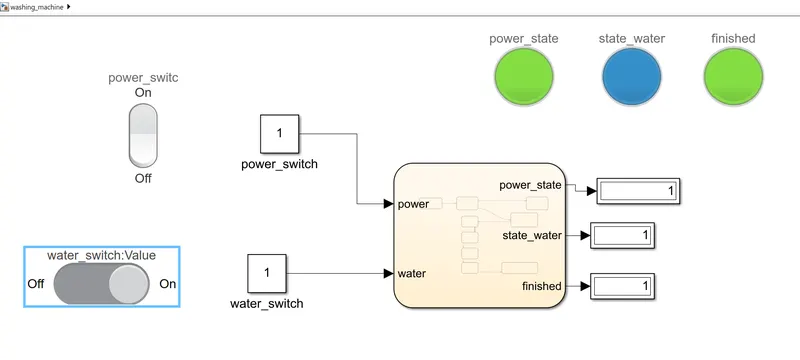
- If the water is 1(ON), the the next state is activated with the water LED blue.
- Next, the processes soaking, washing,rinsing and drying are undergone sequentially for a duration of 200,100,20 and 50 seconds respectively.
- After all these processes are completed, the 'finished' LED is ON.
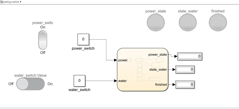
- Rocker switch,Slider switch,constant ,display and LED are the blocks used other than the State flow chart
SIMULATION AFTER RUNNING:
a) When the POWER and WATER switch is OFF:
b)When the POWER switch is ON and WATER switch is OFF:
c)When both the POWER and WATER switch is ON:
RESULT:
The control logic of a “washing machine” using Stateflow as per given sequence was implemented successfully
-------------------------------------------------------------------------------------------------------------------------------------------------
OBJECTIVE 2:
To make a Simulink chart for the “Gear shift” logic as per below conditions:
Speed Range(kmph) Gear
0 to 15 1
16 to 25 2
26 to 40 3
41 to 60 4
Above 61 5
Give speed input while the simulation is running & display the gear number.
THEORY:
- A transmission is a machine in a power transmission system, which provides controlled application of power. Often the term 5-speed transmission refers simply to the gearbox, that uses gears and gear trains to provide speed and torque block conversions from a rotating power source to another device.
- The most common use is in motor vehicles, where the transmission adapts the output of the internal combustion engine to the drive wheels. Such engines need to operate at a relatively high rotational speed, which is inappropriate for starting, stopping, and slower travel. The transmission reduces the higher engine speed to the slower wheel speed, increasing torque in the process.
- Often, a transmission has multiple gear ratios (or simply "gears") with the ability to switch between them as the speed varies. This switching may be done manually (by the operator) or automatically (by a control unit).
MODEL:
LOGIC AND EXPLANATION:
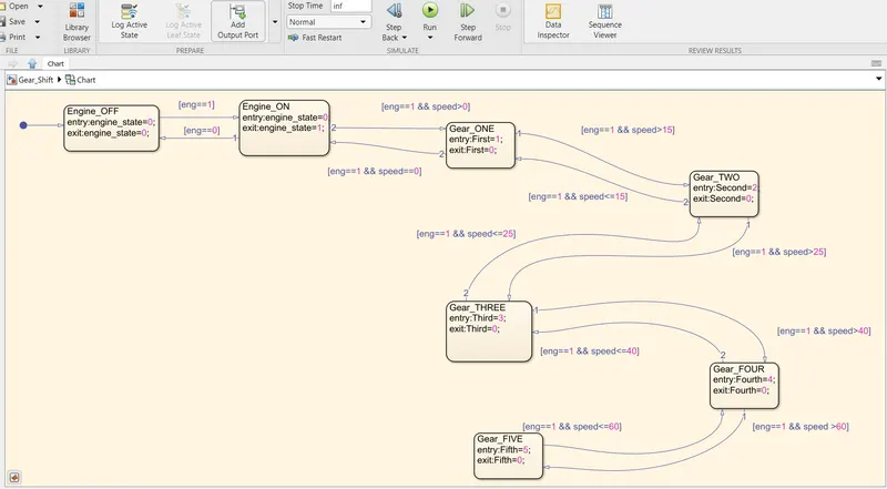
- Engine Power and speed are the inputs.
- The first block is the engine power block.If the engine is ON, then the process moves to the next block.
- If the speed is > 0, the transmission is in first gear.
- If the speed is >15, then the power is transmitted to through the second gear.
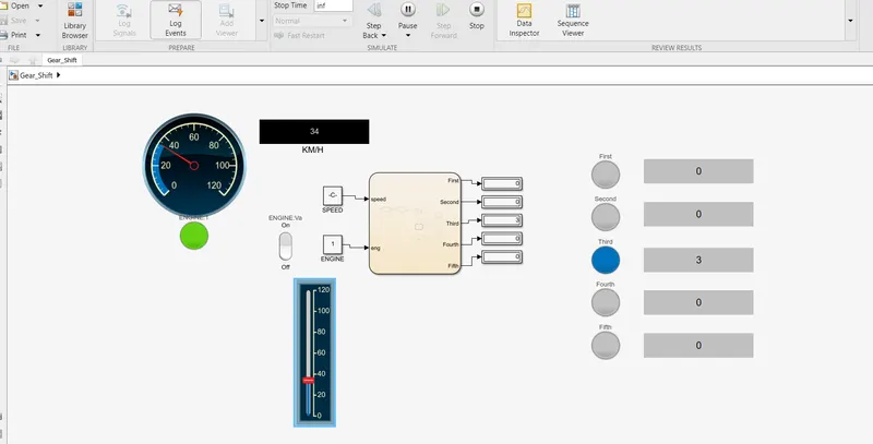
- If the speed is >25, the thrid gear is activated.
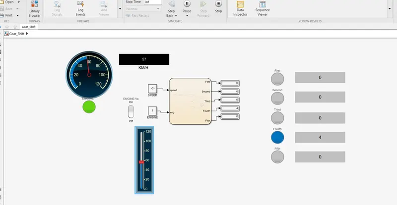
- If the speed is >40, the fourth gear is activated.
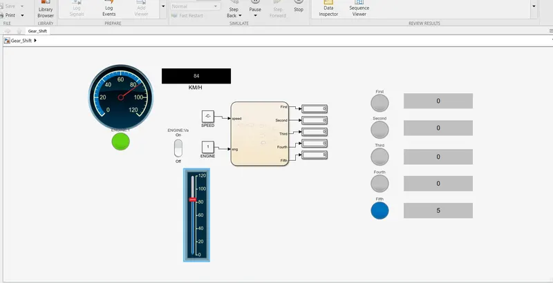
- If the speed is >60, the fifth gear is activated.
- If the speed is reduced, the downshift happens accordingly.
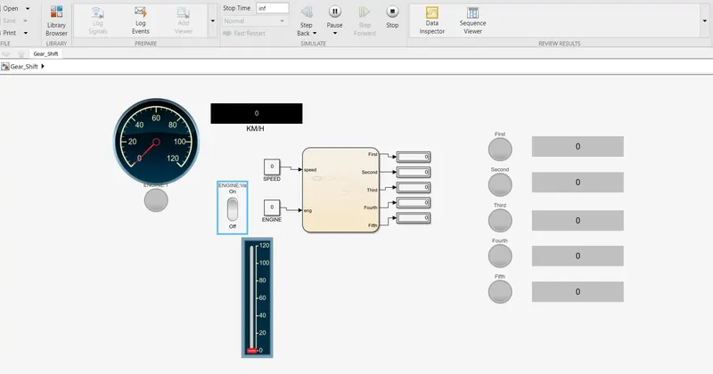
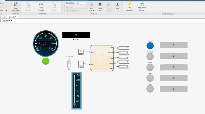
- The vertical slider block is used to change the speed.
- The circular gauge is used to denote the speed.
- Display,rocker switch,LED are among the blocks used other than the State flow chart.
SIMULATION AFTER RUNNING:
a) When the Engine is OFF
b) When the Engine is turned ON and the speed is 10km/hr:
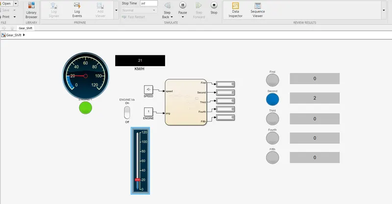
b)When the speed is 21km/hr:
c)When the speed is 34km/hr:
d)When the speed is 57km/hr:
e)When the speed is 84km/hr:
RESULT:
The control logic of a “Gear Shift” using Stateflow as per given sequence was implemented successfully.