Week -2
1) OBJECTIVE:
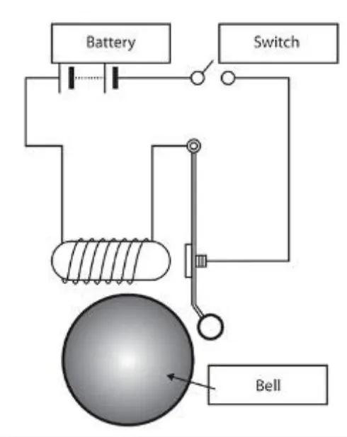
- To make a simulink model of a Doorbell using solenoid block according to the arrangement given below:
-
Create a situation where the switch is closed for 2 seconds and then released. Observe the physical movement of the plunger. Assume remaining parameters.
THEORY:
- Solenoid: A solenoid is a device comprised of a coil of wire, the housing and a moveable plunger (armature). When an electrical current is introduced, a magnetic field forms around the coil which draws the plunger in. More simply, a solenoid converts electrical energy into mechanical work.
- In the above arrangement, when the switch is closed the electromagnet receives electrical power from the battery and pulls the metal arm to hit the bell producing sound.
SIMULINK MODEL:
EXPLANATION:
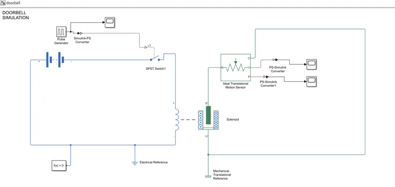
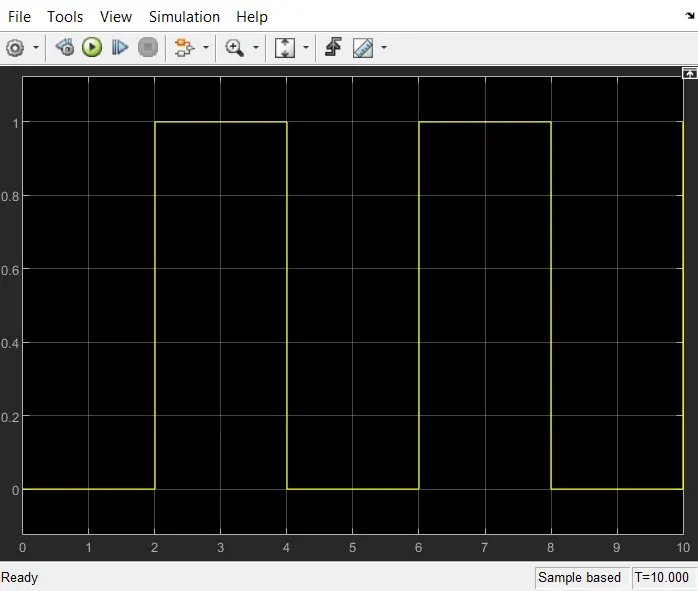
- A pulse generator block with the following parameters; Amplitude:1, Period:4 secs,Pulse width:50% of period and a Phase delay of 2 secs is used to supply the external control signal to the SPST switch.
- The switch is the connected to battery block and a solenoid block.
- The C and R ports of the Solenoid is connected to the C and R port of the the Ideal Translational Motion Sensor block respectively. A positive current from the electrical + to - ports creates a negative force (i.e., a pulling force) from the mechanical C to R ports.
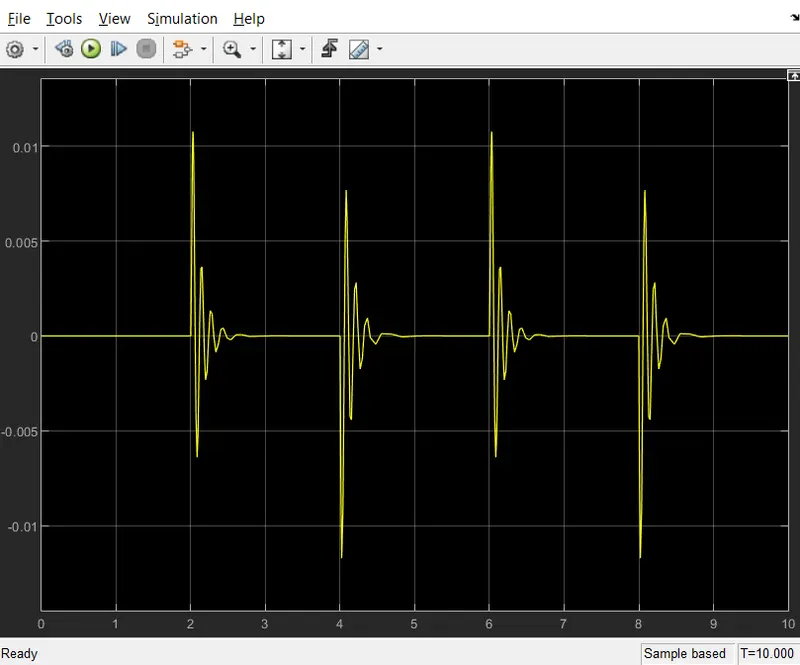
- The physical signal ports V and P report the velocity and position, respectively, of port R relative to port C. The measured velocity is positive when the velocity at port R is greater than the velocity at port C.
- The ports V and P are connected to scopes to display the respective output signals.
- Simulink-PS Converter and PS-Simulink Converter is used to convert the simulink signals to physical signals and vice-versa respectively.
- Electrical Reference ,Mechanical Translational Reference and Solver configuration blocks are also added accordingly to run the simulation.
SCREENSHOTS:
- INPUT SIGNAL:
- OUTPUTS:
(i) Velocity(m/s):
(ii) Position(m):
CONCLUSIONS:
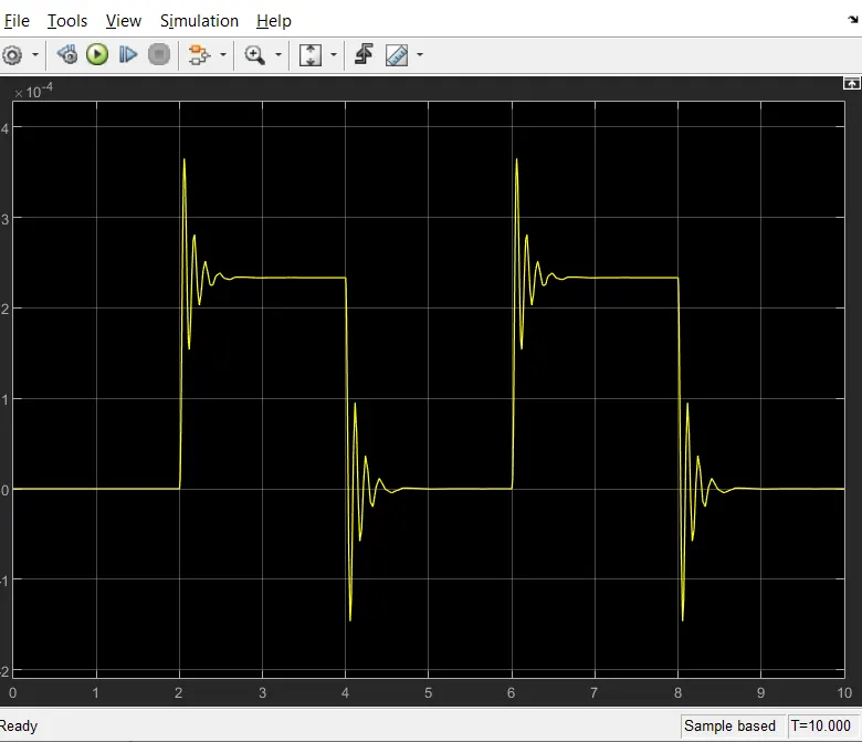
- The simulation was run for 10s and the position and velocity characteristics of the plunger was obtained.
--------------------------------------------------------------------------------------------------------------------------------------------------------------------------------------------------------------------------------------------
2) OBJECTIVE:
- To make a simulink model that uses a thermistor to sense the temperature of a heater & turn on or turn off the fan as per below conditions:
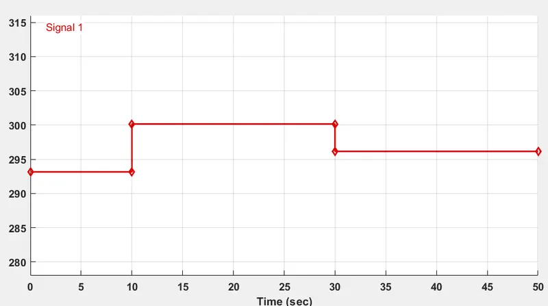
(i) Temperature source: 20 °C from 0 to 10 seconds, 27 °C from 10 to 30 seconds, 23 °C from 30 to 50 seconds
(ii) Fan conditions: ON if the temperature above 25 °C, OFF otherwise
THEORY:
A thermistor is a type of resistor that has a resistance capacity more than a conducting material and less than an insulating material. Its resistance is strongly dependent on temperature , more so than in standard resistors.
Depending on materials used, thermistors are classified into two types:
- With NTC thermistors, resistance decreases as temperature rises; usually due to an increase in conduction electrons bumped up by thermal agitation from valency band. An NTC is commonly used as a temperature sensor, or in series with a circuit as an inrush current limiter.
- With PTC thermistors, resistance increases as temperature rises; usually due to increased thermal lattice agitations particularly those of impurities and imperfections. PTC thermistors are commonly installed in series with a circuit, and used to protect against overcurrent conditions, as resettable fuses.
Thermistors are widely used as inrush current limiters, temperature sensors , self-resetting overcurrent protectors, and self-regulating heating elements. An operational temperature range of a thermistor is dependent on the probe type and is typically in between −100 °C (173 K) and 300 °C (573 K).
SIMULINK MODEL:
EXPLANATION:
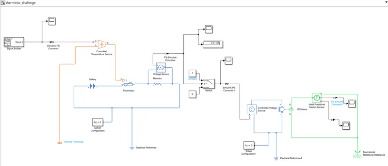
- A Signal Builder block is used to generate a signal according to the given temperature conditions
- The generated signal is connected to the S port of Controlled Temperature Source block to maintain a controlled temperature difference regardless of the heat flow rate. The temperature difference is set by the physical signal port S.
- The port A is connected to a thermal reference. The port B is connected to Thermal port of the Thermistor (NTC)block.
- The electrical ports of the thermistor is connected to battery,resistor and electrical reference to form a closed circuit.
- A Voltage Sensor block is connected in parallel with the resistor.
- The voltage sensor was connected to a SPST switch, which is connected to a Constant Voltage Source block to maintain a specified voltage at its output regardless of the current passing through it
- The Constant Voltage Source is connected to the electrical ports of a DC motor.
- The mechanical C and R ports of the DC motor is then connected to the respective C and R ports of an Ideal Rotational Motion sensor.
- The W and A ports of the Ideal Rotational Motion sensor was then connected to scopes to display the outputs.
- Simulink-PS Converter and PS-Simulink Converter is used to convert the simulink signals to physical signals and vice-versa respectively.
- Electrical Reference ,Mechanical Rotational Reference, Thermal Reference and Solver configuration blocks are also added accordingly to run the simulation.
WORKING:
- The model was run by generating the signal initially for the temperature condtion 298.15 K (25 °C) and the voltage was note as 0.01196 V.
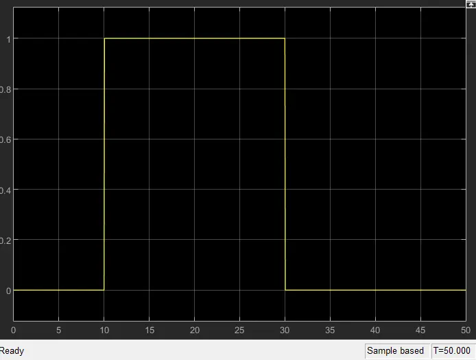
- This voltage was given as the threshold for the switch. Here, the switch is ON(1) when the voltage is above the threshold and OFF(0) otherwise.
- The model was then run by generating the signal for the required temperature condtions: 293.15 K(20 °C) from 0 to 10 seconds, 300.15 K (27 °C) from 10 to 30 seconds, 296.15 K(23 °C) from 30 to 50 seconds.
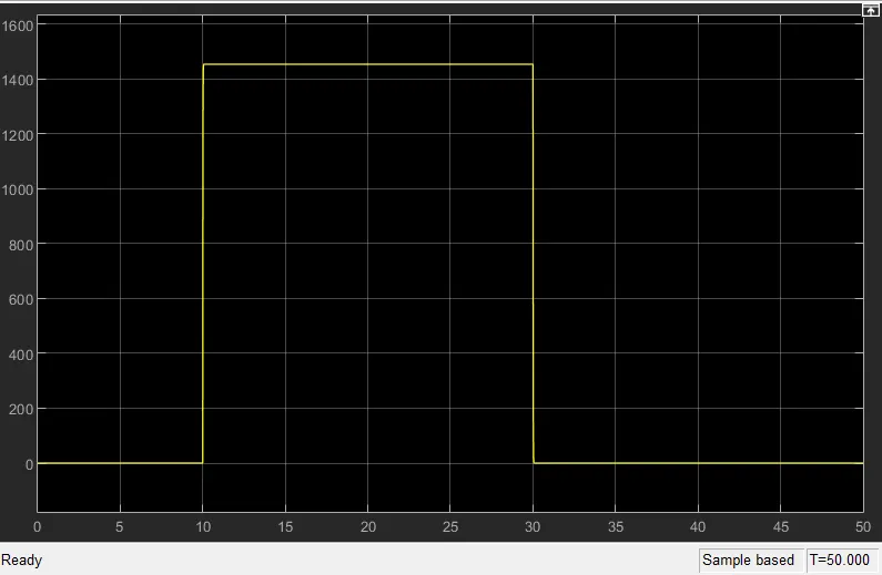
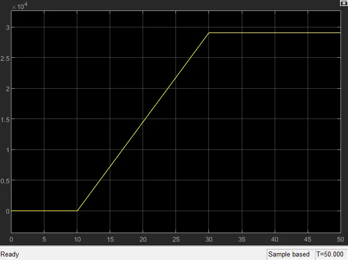
- The Angular Velocity and Anglur Displacement of the FAN(DC motor) was obtained from the output scopes.
SCREENSHOTS:
INPUT:
OUTPUTS:
a)SWITCH Status:
b) Angular Velocity(rad/s) of the FAN(DC motor) when the switch is ON and OFF.
c) Angular Displacement(rad) of the FAN(DC motor) when the switch is ON and OFF.
CONCLUSION:
The SIMULINK model was run for the stop time of 50 seconds.
- The switch was ON for the simulation time 10 to 30 seconds since the temperature was above 25°C.
- The Angular Velocity and Angular Displacement of the fan was obtained.