Project
BAJA ALL-TERRAIN VEHICLE(ATV) WITH CONTINUOUSLY VARIABLE TRANSMISSION MODEL STUDY REPORT
OBJECTIVE:
To carry out a system level simulation and study of the simulink model "Baja All-Terrain Vehicle(ATV) with Continuously Variable Transmission(CVT)" and the explain about the findings.
About BAJA:
Baja SAE is an Collegiate Design Series competition run by the Society of Automotive Engineers International (SAE International). Teams of students from universities all over the world design and build small off-road cars. The cars all have engines of the same specifications. As of 2018 the engine has been an unmodified Briggs & Stratton Model 19 Vanguard engine single-cylinder with a displacement of 305cc and power output of approximately 10 bhp (7.5 kW).
The goal in Baja SAE racing is to design, build and race off-road vehicles that can withstand the harshest elements of rough terrain. The vehicles used in Baja SAE racing are often similar in appearance to dune buggies. Before 2007, the events were called "Mini Baja".All cars must adhere to SAE International's rules, and pass SAE's technical inspection and judging; a car may not race until all safety inspections are passed.
Continuously Variable Transmission (CVT):
A continuously variable transmission (CVT) is an automatic transmission that can change seamlessly through a continuous range of gear ratios. This contrasts with other transmissions that provide a limited number of gear ratios in fixed steps. The flexibility of a CVT with suitable control may allow the engine to operate at a constant RPM while the vehicle moves at varying speeds.
The most common type of CVT uses a V-belt which runs between two variable-diameter pulleys. The pulleys consist of two cone-shaped halves that move together and apart. The V-belt runs between these two halves, so the effective diameter of the pulley is dependent on the distance between the two halves of the pulley. The V-shaped cross-section of the belt causes it to ride higher on one pulley and lower on the other; therefore, the gear ratio is adjusted by moving the two sheaves of one pulley closer together and the two sheaves of the other pulley farther apart.
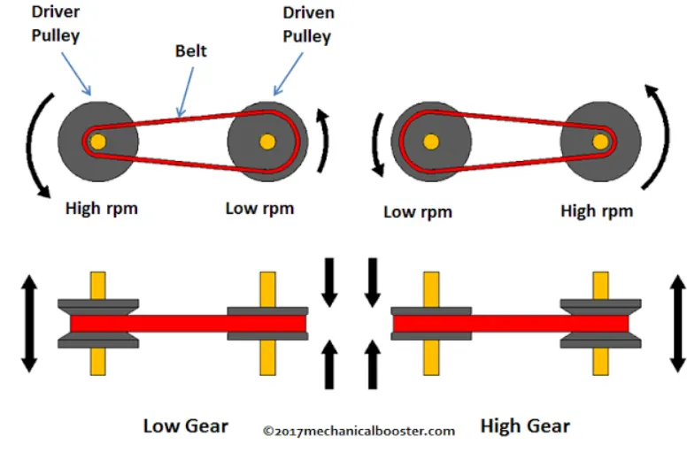
As the distance between the pulleys and the length of the belt does not change, both pulleys must be adjusted (one bigger, the other smaller) simultaneously in order to maintain the proper amount of tension on the belt. Simple CVTs combining a centrifugal drive pulley with a spring-loaded driven pulley often use belt tension to effect the conforming adjustments in the driven pulley. The V-belt needs to be very stiff in the pulley's axial direction in order to make only short radial movements while sliding in and out of the pulleys.
A belt-driven design offers approximately 88% efficiency, which, while lower than that of a manual transmission, can be offset by enabling the engine to run at its most efficient RPM regardless of the vehicle's speed. When power is more important than economy, the ratio of the CVT can be changed to allow the engine to turn at the RPM at which it produces the greatest power.
SIMULINK Model Abstract:
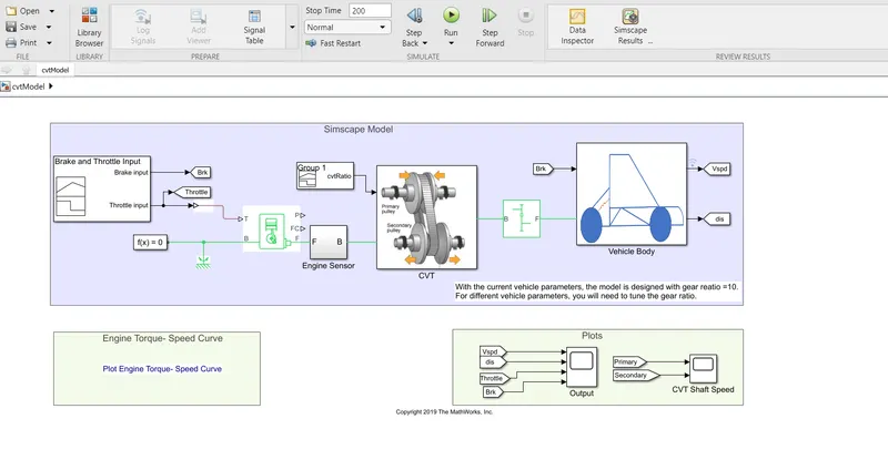
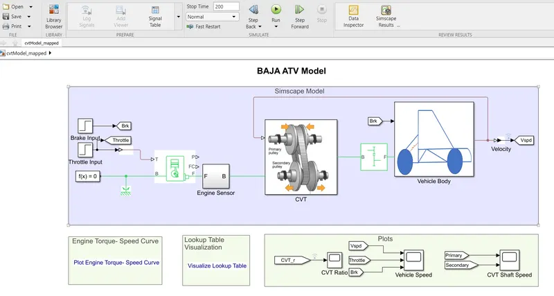
- This model consists of blocks that represents the different components of an ATV with CVT. Throttle and Brake inputs is are given to the Generic Engine block which in turn is connected to the CVT transmission and from there to the vehicle body.
- Four models with slight variations are studied.
OPEN LOOP MODELS:
------------------------------------------------------------(i) Main Model-----------------------------------------------------------------
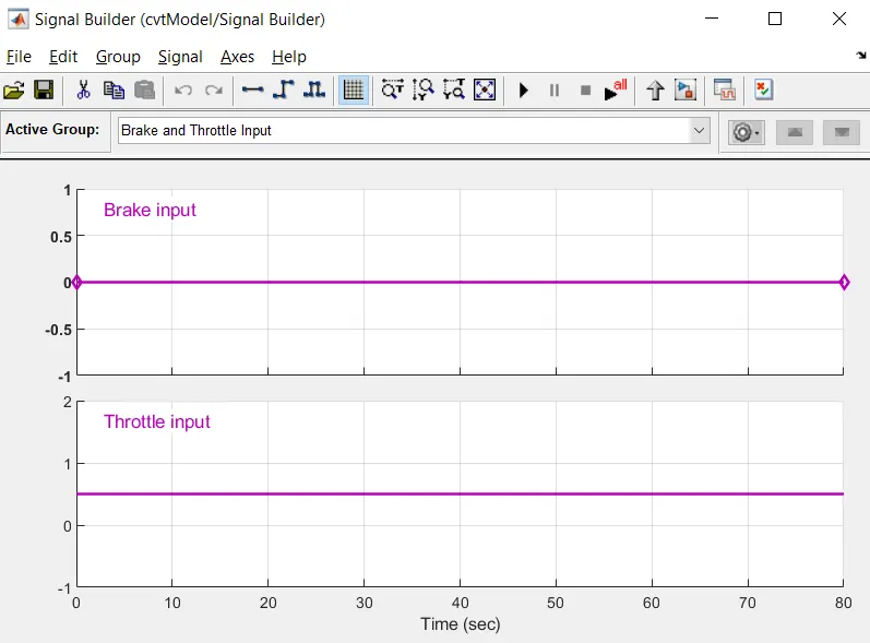
This model is basically a simple model where constant signals are given as the throttle and braking inputs using the signal builder block.
INPUTS:
MAIN COMPONENTS/BLOCKS:
GENERIC ENGINE:
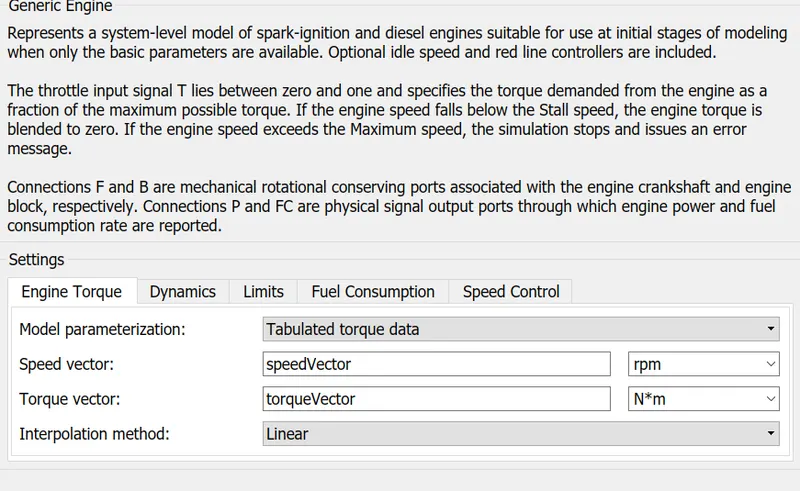
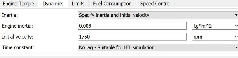
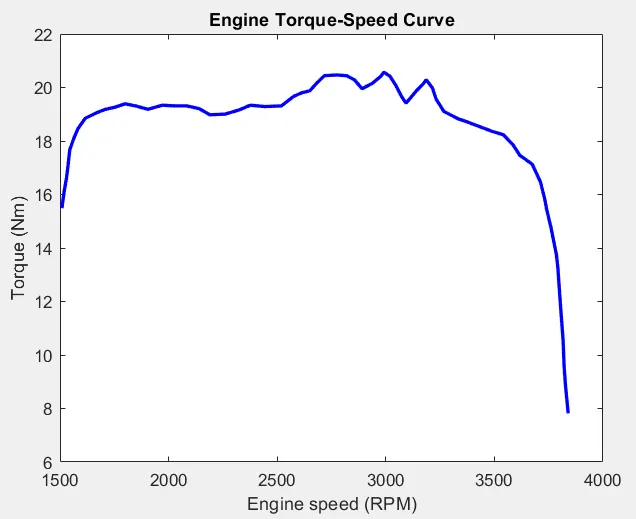
- The speed and input vectors were loaded from the base workspace.
- The engine inertia and inital velocity was set to 0.008 kg*m^2 and 1750 rpm respectively.
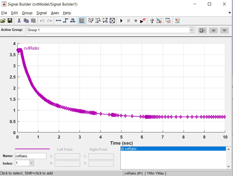
CVT RATIO:
CVT SUB-SYSTEM:
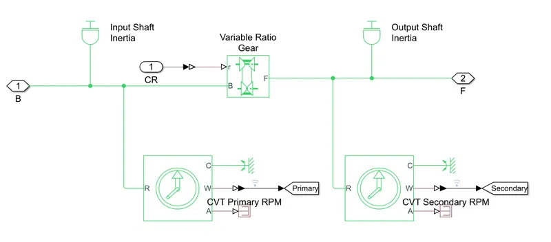
- This system consists of the input and output shaft inertial blocks which represents the primary and secondary pulley, a variable gear ratio (from the cvt ratio signal) and ideal rotational motion sensors for the primary and secondary pulleys .
SIMPLE GEAR:

A simple gear with a certain gear ratio is used for speed reduction from the cvt to the body dynamics
VEHICLE BODY SUB-SYSTEM:
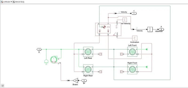
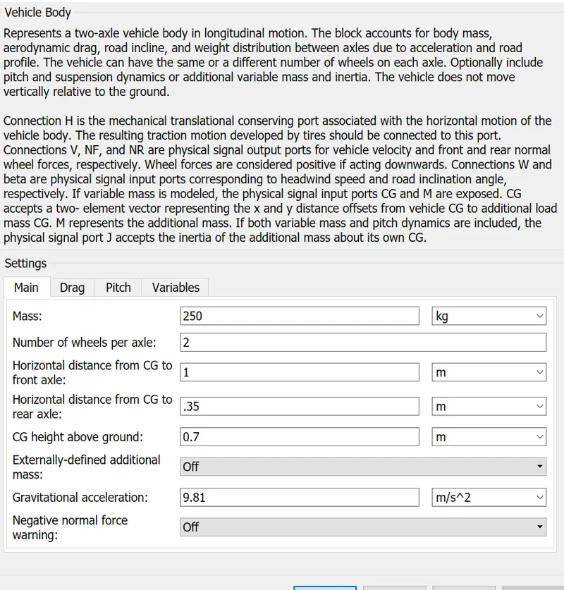
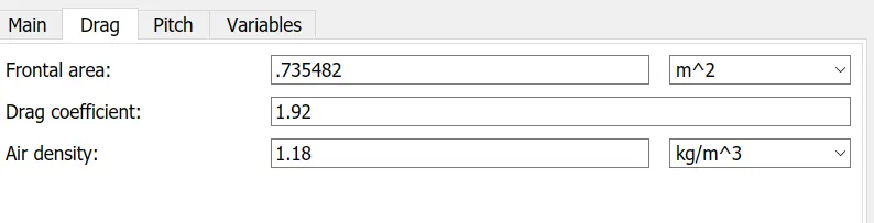
- In this block, the necessary parameters related to the vehicle body dynamics is configured. In the case here, it's mostly basic.
OUTPUTS:
- In this first model, the throttle was given as 0.5 with the brake nil.
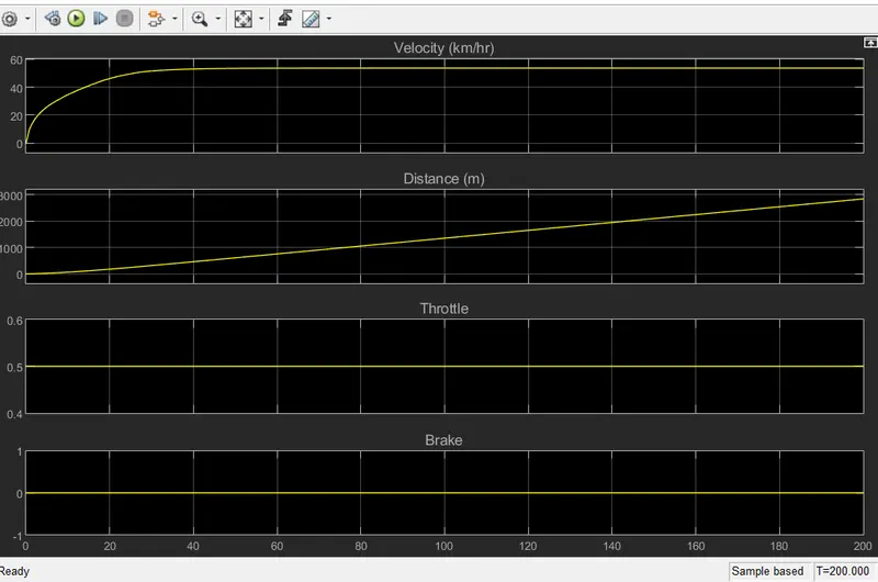
- Here, the velocity increased at a decreasing rate initially until a constant velocity was obtained after almost 60 seconds while the distance covered was linear in nature.
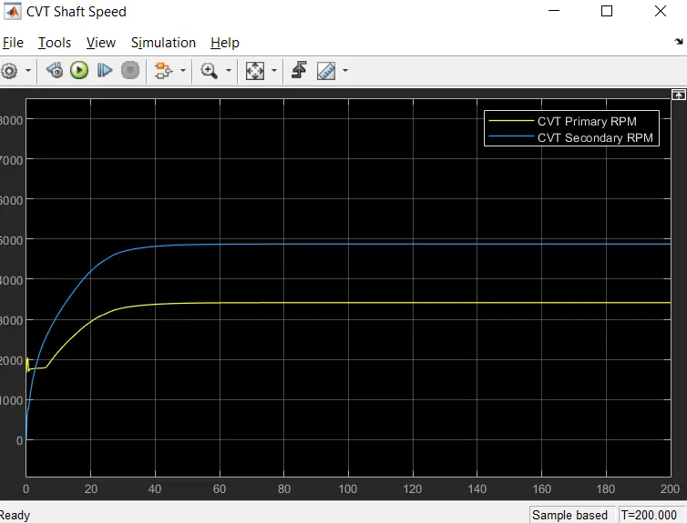
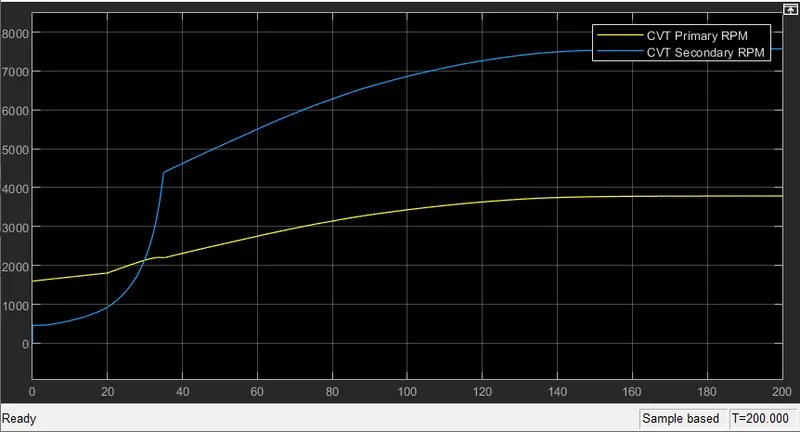
- The rpm change of the primary and secondary pulleys can be also observed.
- The secondary pulley which started at low rpm overtook the primary pulley's rpm within seconds.
---------------------------------------(ii) Main Model with Dashboard configuration-------------------------------------------------------------
This model is same as model (i),but the throttle and braking inputs can be varied during the simulation with the help of knob.
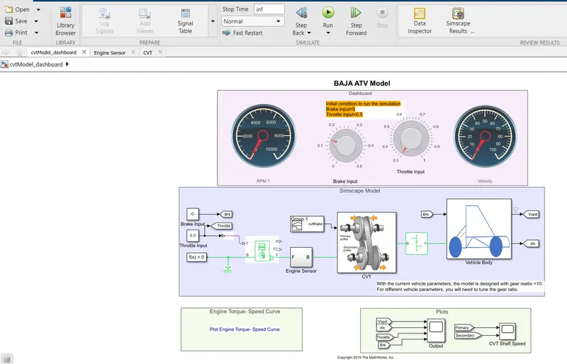
- The only difference between this model and the main model(i) is that here,the inputs are can be changed during the simulation which is stop times as infinity.
PLOTS:
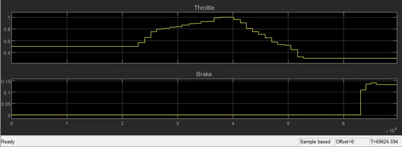
- These were the nature of the throttle and braking given:
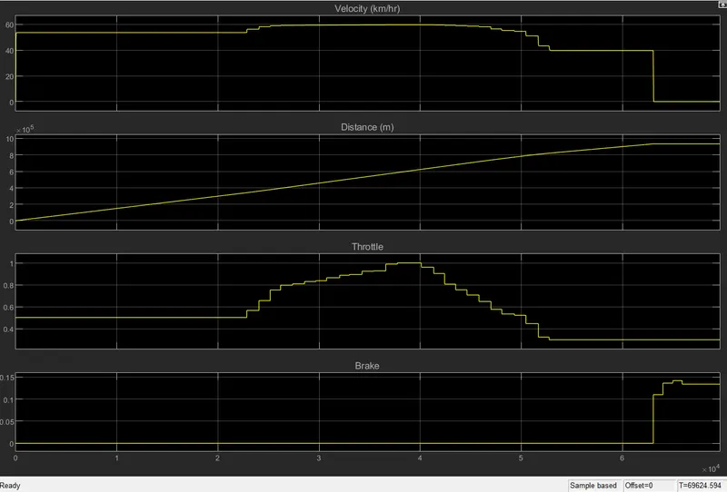
- And these were the nature of the velocity and distance with respect to the inputs given:
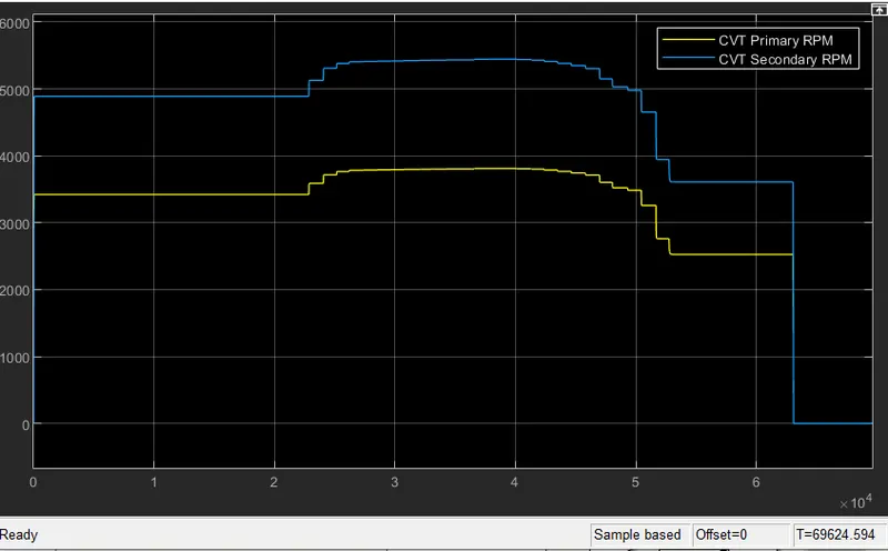
- The CVT primary and seconday pulley rpm relation:
CLOSED LOOP MODELS:
---------------------------------------(iii) Main Model with mapped configuration-------------------------------------------------------------
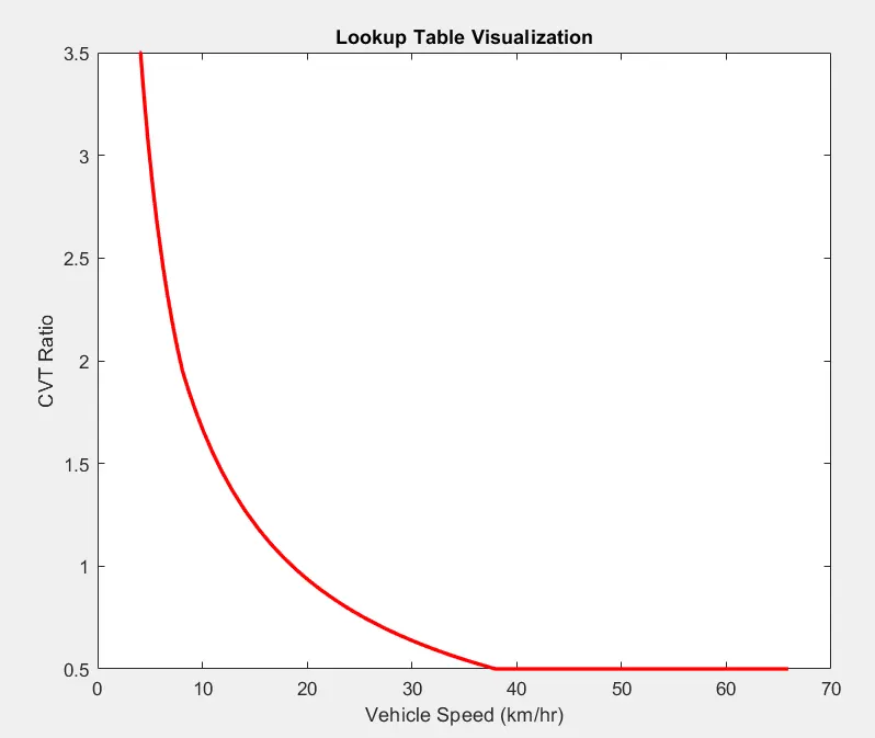
This model uses the cvt ratio from the the lookup cable created by using a script and also uses step block for the throttle and brake inputs. Also, the real-time velocity data is fed into the cvt ratio for more realistic data.
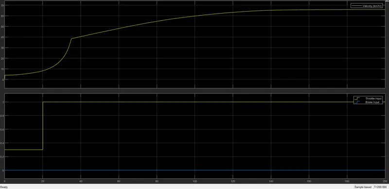
The Acceleration with respect to the throttle and brake input.
- The CVT primary and seconday pulley rpm relation:
---------------------------------------(iv) Main Model with mapped configuration with dashboard-------------------------------------------------------------
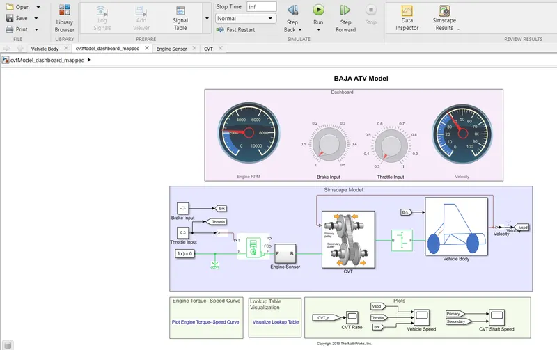
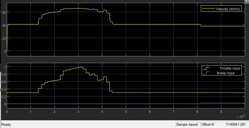
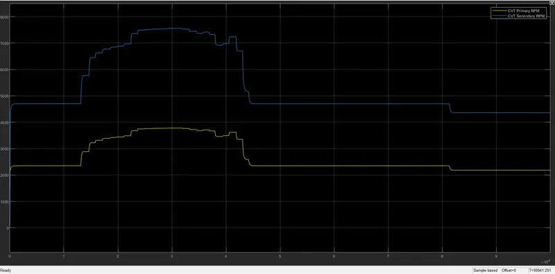
This model is al same as the model(iii), but uses knobs to change the throttle and brake during the simulation.
The Acceleration with respect to the throttle and brake input.
- The CVT primary and seconday pulley rpm relation:
CONCLUSION:
- In conclusion, the above mentioned plots are the results from the default parameter from the model.
- In addition to that, some other interesting studies was also done.
- The simple gear block was used for the speed reduction from the transmission to the drive train.
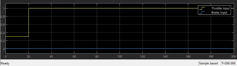
- The following relations were obtained for the simple gear ratios: 2 ,4 and 10 after running the model (iii) with the inputs.
The acceleration(velocity vs time):
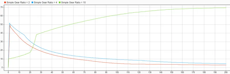
- Here, we can see how the velocity increases with respect to time at high gear ratio.
- For lower gear ratios, the acceleration is rapid initially for short time and then decelerates
The Engine RPM:
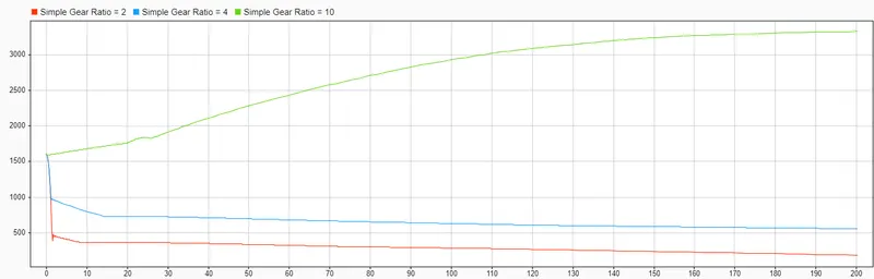
- The engine RPM for the different gear ratios.
This model is useful in obtaining the necessary data to build a BAJA ATV.
Various types of data can be obtained with different vehicle parameters.