Week - 4
AIM:
- To Implement control logic of a “washing machine” using Stateflow as per given sequence:
- If the power supply is available, the system gets activated
- If the Water supply is not available, stop the process & indicate through LED
- Soaking time should be 200s followed by Washing time of 100s.
- Then rinsing happens for next 20s & dryer runs for 50s
To turn on the finished LED after all the processes have completed.
- To make a Simulink chart for the “Gear shift” logic as per below conditions:
|
Speed range |
Gear |
|
0 to 15 |
1 |
|
16 to 25 |
2 |
|
26 to 40 |
3 |
|
41 to 60 |
4 |
|
Above 61 |
5 |
BODY OF CONTENT:
- CONTROL LOGIC OF A WASHING MACHINE:
Blocks used:
Constant: To give the input of power supply and water supply to the system.
Chart: To implement the stateflow of the process in washing machine as flow chart.
Display: To display the output of the stateflow in the chart.
Lamp: The Lamp block displays a color to indicate the value of the input signal.
Rocker switch: The Rocker Switch block toggles the value of the connected block parameter between two values during simulation. It is used to ON and OFF the power supply and water supply.
To create this control system on Simulink insert the chart and create the logic system using stateflow.
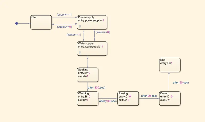
Stateflow of Washing process:
Explanation:
The first state box represents the start of the process. If the power supply is on, then it moves to the next state of ‘Power supply’ or else it terminates the flow.
The next state operates if the water supply is ON or else the flow terminates.
The next comes soaking process where at entry, the assigned variable ‘A=0’. After execution of the process, the assigned variable ‘A=1’.
After 200 seconds, the process moves to ‘Washing’ where at entry, the assigned variable ‘B=0’ and at exit the assigned variable ‘B=1’ after 100 seconds.
Then it moves to ‘Rinsing’ process. At entry the assigned variable ‘C=0’ and after 20 seconds the assigned variable ‘C=1’.
Next moves to ‘Drying’ part which takes for 50 seconds with assigned variable ‘D’ and finally ‘End’.
SIMULINK MODEL FOR WORKING OF ‘WASHING MACHINE’:
Explanation:
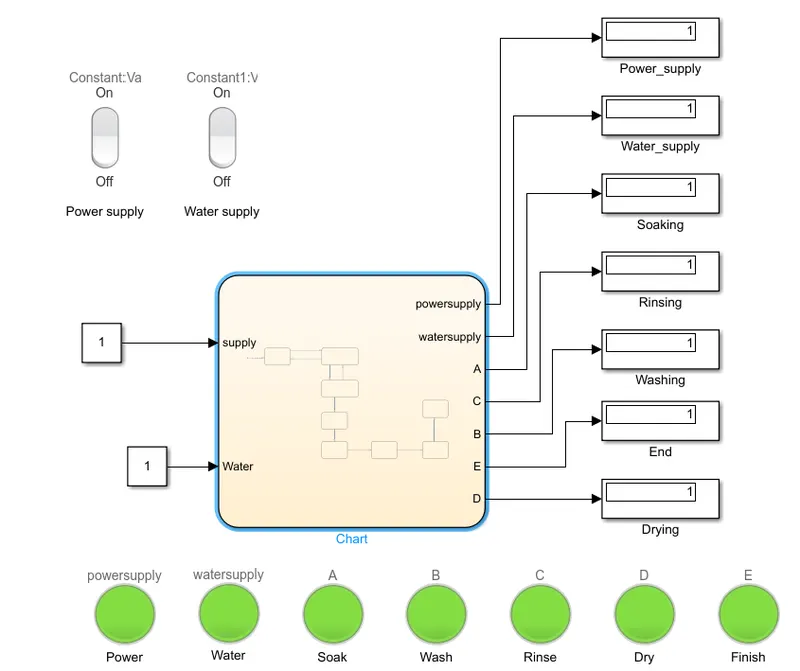
The inputs ‘Power supply’ and ‘Water supply’ is connected to the stateflow of the chart and the output of the stateflow is displayed in the ‘Display’ block.
To indicate whether each of the process is finished in the stateflow, the lamp block is selected and connected to the respective process in the stateflow.
The ‘Rocker switch’ block is selected to connect the switch with input power and water supply. Thus it is connected to the input constants of supply and water.
Case1: Power supply OFF and Water supply OFF
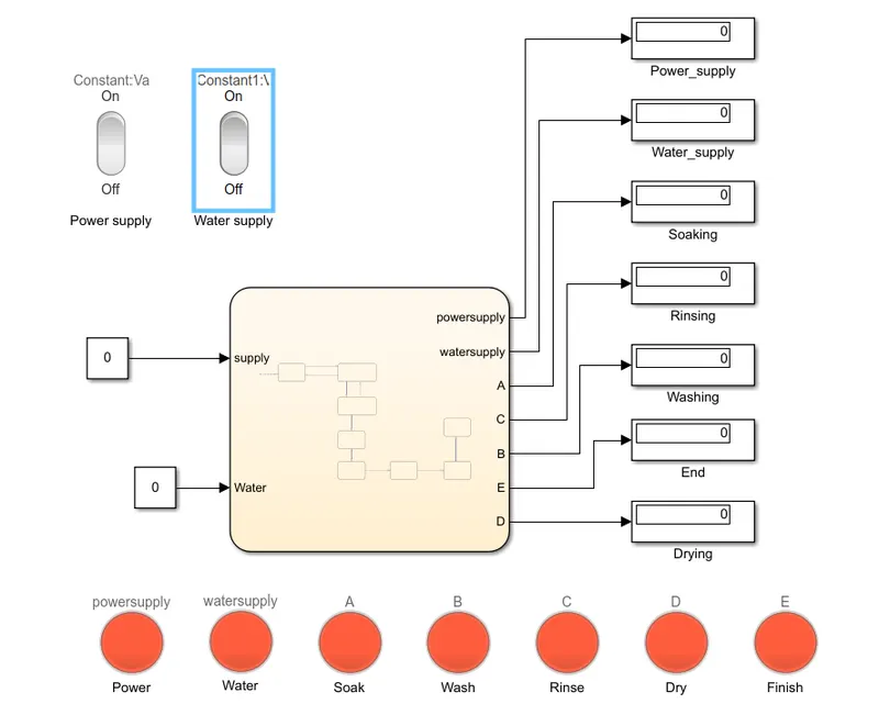
Since the power and water supply both are at OFF condition, the output result shows ‘0’ in the display and the lamp displays ‘red’ color which indicates process has not finished.
Case2: Power supply ON and Water supply OFF
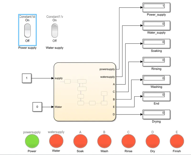
Since the power is ON and water supply is OFF condition, the output result shows ‘1’ in the display of power supply and ‘0’ in rest all displays and the power lamp displays ‘green’ which indicates that power is ON and rest displays ‘red’ color which indicates process has not finished.
Case3: Power supply ON and Water supply ON
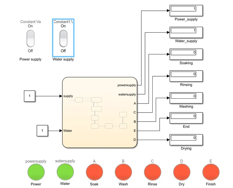
Since the power is ON and water supply is ON condition, the output result shows ‘1’ in the display of power supply and water supply and ‘0’ in rest all displays and the power lamp displays ‘green’ which indicates that power and water supply is ON and rest displays ‘red’ color which indicates process has not finished since the time allotted is only 10 seconds.
As we increase the time of simulation, each of the process occur step by step with its allotted time and finally the entire process is finished when the simulation time is entered as the whole process time. Here we give the simulation time as 450 seconds so that the entire process gets completed.
Case4: Power supply ON and Water supply ON with simulation time of 450 seconds
2. SIMULINK CHART FOR GEAR SHIFTING:
Blocks used:
Constant: To give the input of speed of the chart model.
Slider gain: To give speed input, constant block alone is not enough. We need to use a "slider gain" which will be able to change the input value during the run time of the simulation. While using the slider gain block it has an input that needs to connect with a constant.
Chart: To implement the stateflow of the process in gear shifting as the speed varies which is given as input.
Display: To display at which gear, the car is running is shown in ‘Display’ block.
Lamp: This highlights the gear number of the vehicle by ‘green’ light.
Stateflow model of gear shifting:
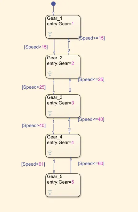
As per the given speed range, the stateflow is arranged and gear shifting is done.
Simulink model for ‘Gear shifting’:
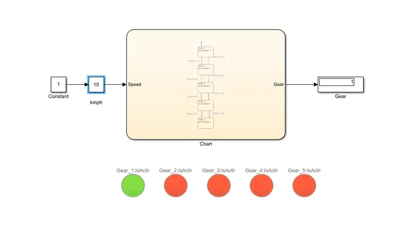
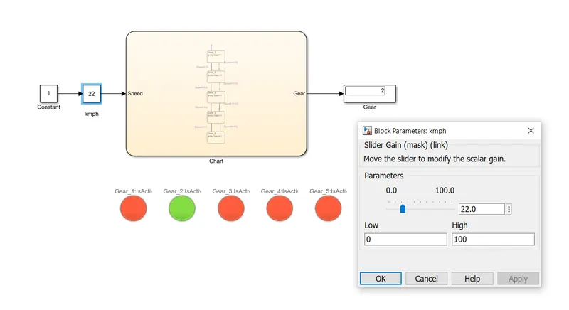
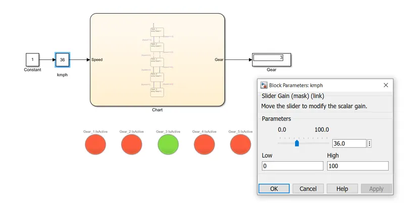
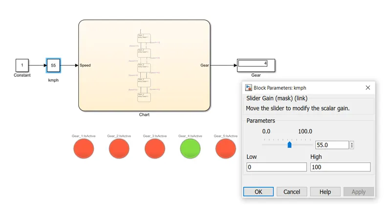
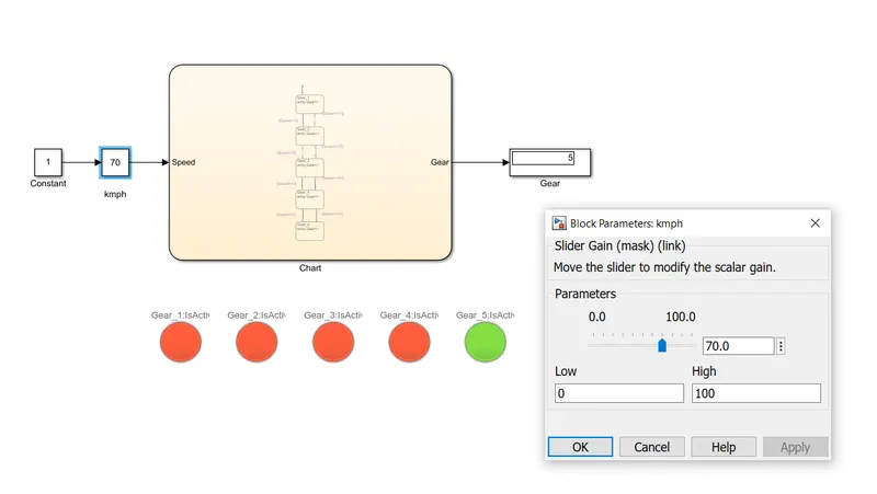
Here, the constant block is connected to the slider gain block to change the input value during the run time of the simulation. While using the slider gain block it has an input that needs to connect with a constant. Then the slider gain is connected to the chart which has stateflow process. Depending upon the input value given in the slider gain, the gear is shifted and shown in the ‘Display’ block. Lamp is also connected to the stateflow in chart where as the speed changes, the gear is shifted and the current gear is highlighted as ‘green’ colour and the rest is highlighted as ‘red’ colour.
CONCLUSION:
- Thus, the control logic of a “washing machine” using Stateflow as per given sequence is implemented and the result is obtained for the respective inputs.
- The Simulink chart for the “Gear shift” logic as per given conditions is made and results are shown with various speed ranges.