Using Stateflow to work a Washing Machine and Gearbox using Simulink
Week4 Challenge
AIM: 1.To Implement a control logic of a “washing machine” using Stateflow as per the given sequence:
- If the power supply is available, the system gets activated
- If the Water supply is not available, stop the process & indicate through LED
- Soaking time should be 200s followed by Washing time of 100s.
- Then rinsing happens for the next 20s & dryer runs for 50s
- After all the processes have been completed turn on the finished LED
2.Make a Simulink chart for the “Gear shift” logic as per the below conditions:
Speed Range(km/h) Gear
0 to 15 1
16 to 25 2
26 to 40 3
41 to 60 4
Above 61 5
- Give speed input while the simulation is running & display the gear number.
EXPLANATION:
- State flow: Stateflow provides a graphical language that includes state transition diagrams, flowcharts, state transition tables. by using state flow to describe how Matlab algorithms and Simulink models react to input signals, events, and time-based conditions.
- Control logic: Control logic is a model system logic of a washing machine using state flow.
MODEL1:-Explanation for Control logic of a “washing machine” using State flow
Washing Machine: It is a machine that is capable of handling various tasks like soaking, washing, rinsing, drying within a short period of time. all the task performed by machine is based on the centrifugation. It is a separation process that used centrifugal force to promote accelerated settling of the particle in the solid or liquid mixture.
In other words, a washing machine is a machine that washes dirty clothes.it contains a barrel into which the clothes are placed. this barrel is filled with water and then rotates very quickly to make the water remove the dirt from the cloths. these can help make the clothes cleaner. 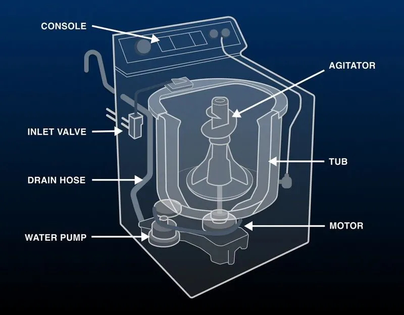
Data:
the different states of washing machines
- Socking-200sec(0-200sec)
- Washing-100sec(200-300sec)
- Rensing-20sec(300-320sec)
- Drying-50sec(320-370sec)
- Finished
Model: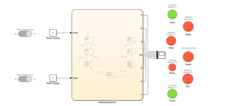
Stateflow: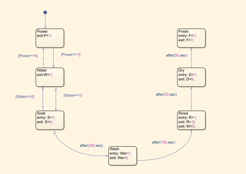
Procedure:
1. I firstly created a slider switch that was connected to the two main constants, i.e the Power Supply and the Water Supply for the Washing machine.
2. So whenever we switch off the switch, the value of the constant changes to zero automatically.
3. Now, the next step was to check if the power has been switched on and to check if the water supply has been switched on.
4. Further we then set up, the signal with the given state flow logic. if the value displayed is 1 then the power and the water supply to the machine. if the value is 0 and 1 then the machine will not start the process as one of the switches is off.
5. When both power and water are at 1 then the socking process starts and runs for 200 sec after this washing started.
6. After 200sec the rinsing process starts. and after this process, the drying process is started for which the water supply is cut off.
7. For all the different processes or states of the machine. the lamp indicates green for working ad red for not working. this gives a better idea to the user, now which process is going on in the machine.
Different Stages of the Washing Machine:
Stage-1: Power check and Water Supply check with soaking done if they are okay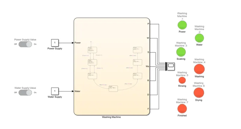
Stage2: Washing completed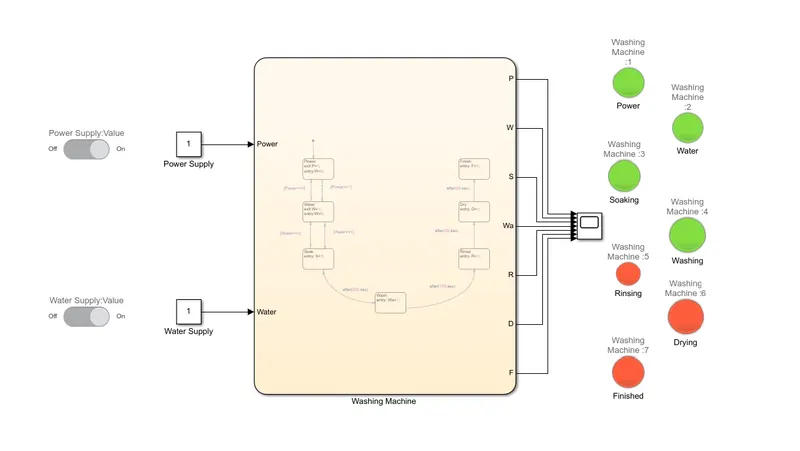
Stage3: Rinsing of the clothes done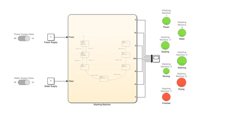
Stage4: Drying completed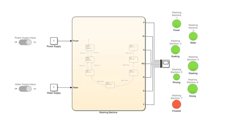
Stage5: All the cycles are completed hence all the finished lamp shows green with all the other lamps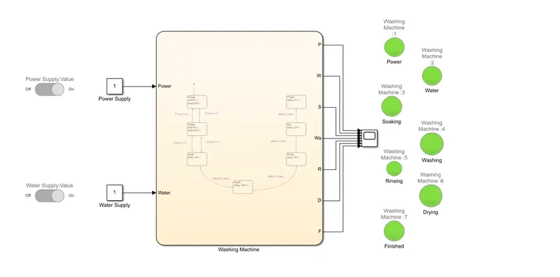
2. Draw Simulink chart for the “Gear shift” logic as per the given conditions:
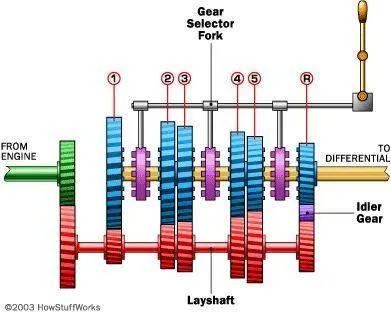
when we push the shifter towards the desired gear the gear looks into the man shaft and rotates it. thus the main shaft rotates at the speed of engaged gear and provides the output as per the gear's ratio. shifting of gears means going from one gear to another by sliding or clicking the shifter. Downshifting means going to lower gears and decreasing the speed and upshifting means going to a higher gear and increase the speed.
Data:
- 1st gear-(0-15kmph)
- 2nd gear-(16-25kmph)
- 3rd gear-(26-40kmph)
- 4th gear-(41-60kmph)
- 5th gear-(greater than 60kmph)
Model: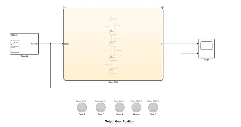
Stateflow: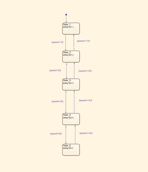
Procedure:
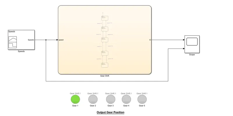
- At the initial position, the slider is at 0.
- According to the given data, the range of the first gear is 0-15kmph.
- The range of the second gear is 15-25kmph.
- The range of the third gear is 25-40kmph.
- The range of the fourth gear is 40-60kmph.
- The range of the fifth gear is greater than 60kmph.
At Gear_1:
At Gear_2: 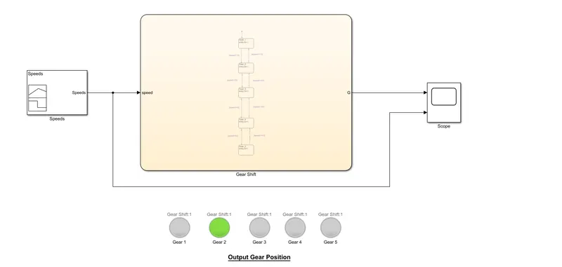
At Gear_3: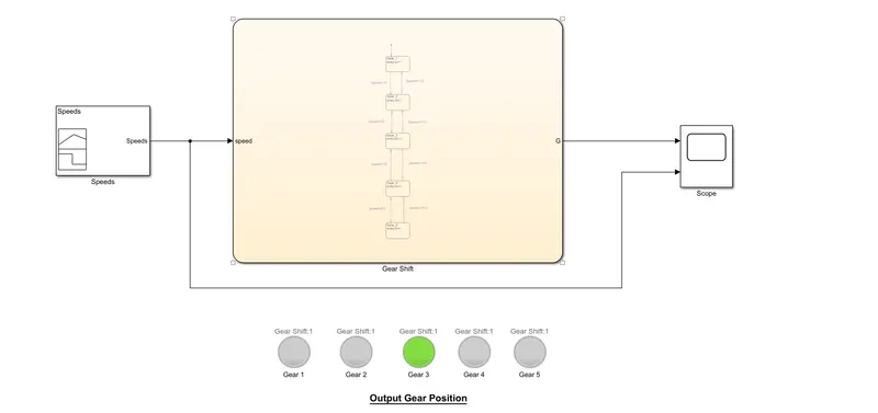
At Gear_4: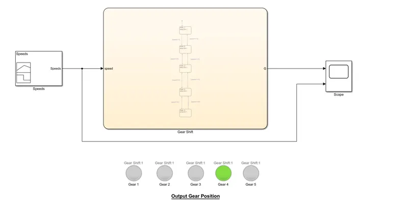
At Gear_5: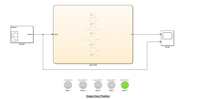
Gear_scope output: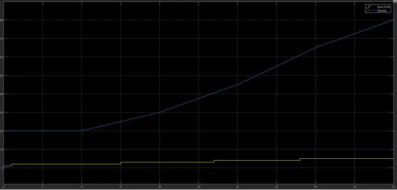
Conclusion: From the output, we can say that the gear shifting takes place according to the given speed input/time changes.