Week - 4
1.AIM:
Implement control logic of a “washing machine” using Stateflow as per given sequence:
- If the power supply is available, the system gets activated.
- If the Water supply is not available, stop the process & indicate through LED
- Soaking time should be 200s followed by Washing time of 100s.
- Then rinsing happens for next 20s & dryer runs for 50s
PROCEDURE:
WORKING PRINCIPLE OF A WASHING MACHINE:
A washing machine by spinning at 800-1600 rpm helps soap and dirt with it to leave the surface of the cloth via centrifugal force and into outlet pipes hence utilizing centrifugation to both clean and partially dry the clothes loaded in it. Thus the processes are electrically controlled, such as the drum, valves, pump, motor and heating. The valve opens again and the dirty water drains out of the drums. The pump works to help get rid of the water. The valve lets clean water in again into the drums. The four process are:
SOAKING:
It is used to dip clothes in detergent water to remove dirt from the clothes. In this function customer need to select soak from a panel. Soak - This function is available with wash timer, In 42 min of washing 27 min is soak and 15 min machine will wash the clothes.
WASHING:
During the wash cycle, a large plastic agitator (green) turns around, moving your clothes through the water. When the wash is finished, the pump drains the water from the outer drum.
RINSING:
The dirty, soapy water is drained, then the washing machine is refilled and your clothes are "rewashed" in clean water. Spin: All the water is drained completely, then your clothes are spun very fast and excess water is removed thanks to centrifugal force.
DRYER:
They work by pushing warm dry air through your wet washing to extract moisture, then cooling the now humid air in a heat exchanger to condense the moisture, which is collected in a tank or pumped down the drain. The (now dry) air is reheated and the cycle repeats.
CONTROL LOGIC OF WASHING MACHINE AND EXPLANATION:
- To create this control system in simulink insert the chart and create the logic system using stateflow. The stateflow excute the flow of inputs "if" the condition is accept.
- In this control logic the input power is applied to ON the washing machine and the power supply is flow in other system. The conditions are applied to move other sequence of operation in stateflow.
- Water supply is execute when power is ON ,so entry and exit are assigned as value of 0 to 1. While the condition is not ok water supply stops and it will come back to its constant state.
- This process is applied for each flow and time of working in each operations are initiate by sec that are given in question.
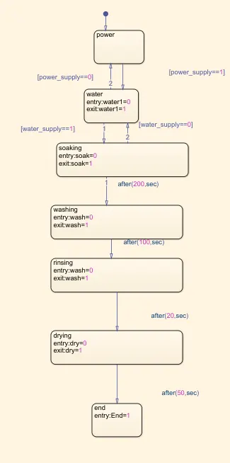
- Now assigned the input values of steadyflow and sequence of operation is initiate to identify the working division. Constant block is created to give an input power value of system.
- And other constant block is created for input of water supply and value as 1 to ON water and to run washing sequence.
- Display block is inserted with each sequence to display the results of operations.
- Lamp block is introduced to indicates wheather the operations are 'ON' or 'OFF' in different states.
RESULT:
Simulink Model are created and inputs are generated to power supply and water supply
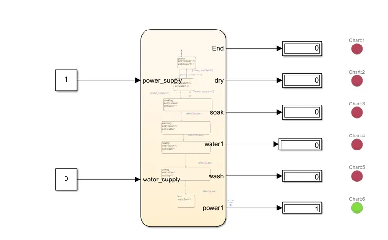
- In this state power supply is assigned as value 1 and water supply remains 0. The power are generated and that indicates as in display value 1 lamp is in green light. But the water supply is 0 so other operations are not proceed that value as 0 and lamp is in red light.
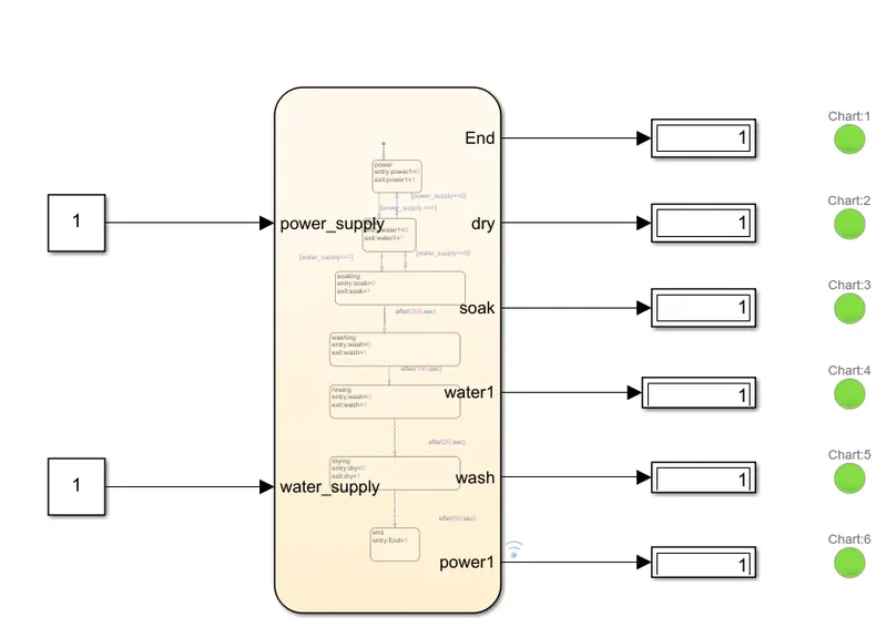
- Now the power supply and water supply value are assigned as 1. Power are generated from input and the operation starts , water supply also done by initiate the value of 1.
- Sequence of operation in stateflow starts when the condition is getting satisfied. Water supply is generated and other operations are followed by duration of time that we given in stateflow.
- Each operations are runned and results are obtained by display block. Lamp is turned "ON" and it indicates green color as result.
2.AIM:
Make a Simulink chart for the “Gear shift” logic as per below conditions:
Speed Range(kmph) Gear
0 to 15 1
16 to 25 2
26 to 40 3
41 to 60 4
Above 61 5
Give speed input while the simulation is running & display the gear number.
GEAR SHIFT:
A manual transmission, also known as a manual gearbox, a standard transmission or colloquially in some countries (e.g. the United states) as a stick shift, is a type of transmission used in motor vehicle applications. It uses a driver-operated clutch, usually engaged and disengaged by a foot pedal or hand lever, for regulating torque transfer from the engine to the transmission; and a gear selector that can be operated by hand.
A conventional 4- or 5-speed manual transmission is often the standard equipment in a modern base model vehicle, with 4-speed being more common in non-passenger vehicles such as pickup trucks and light commercial vehicle. Higher end vehicles, such as sport cars and luxury cars are often usually equipped with a 6-speed transmission for the base model.
SIMULINK MODEL:
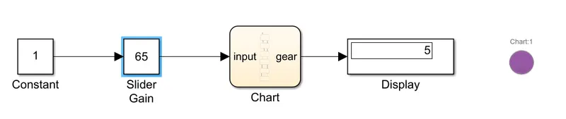
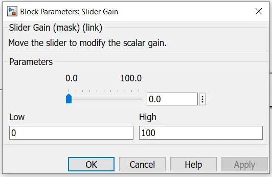
- In this model inputs are generated to slider gain which is connected to constant block the value is 1. The gear shift is acted by conditions in stateflow. Chart is created and conditions are applied same as washing machine stateflow.
- The gear is shited by variations in speed. An speed range are created in chart as several gear system and conditions are applied.
- Display block is used to obtain the result. That displays which gear is running in particular range of speed.
- Lamp is connected to indicate the 5 different colors which is assigned for each gear. The model is shown below,


Speed range and the gear variation are given below,
Speed Range(kmph) Gear
0 to 15 1
16 to 25 2
26 to 40 3
41 to 60 4
Above 61 5
The speed variation are depends on value that initiate in slider gain parameters. when speed range changes the output values of gear also varied by the conditions applied in stateflow.
RESULT:
Gear Neutral
When speed range is 0 the gear is in neutral and output value of display remains 0 thus it indicates red light which are assigned in lamp block.

Gear - 1
When speed range is 0 to 15 the gear 1 is proceed and output value of display gives 1 thus it indicates green light which are assigned in lamp block

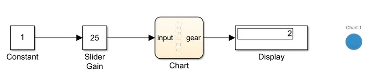
Gear - 2
When speed range is 16 to 25 the gear 2 is proceed and output value of display gives 2 thus it indicates blue light which are assigned in lamp block.
Gear - 3
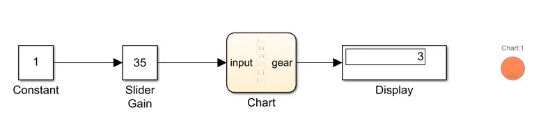
When speed range is 26 to 40 the gear 3 is proceed and output value of display gives 3 thus it indicates orange light which are assigned in lamp block
Gear - 4
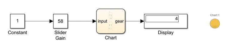
When speed range is 41 to 60 the gear 4 is proceed and output value of display gives 4 thus it indicates yellow light which are assigned in lamp block.
Gear - 5
When speed range is Above 61 the gear 5 is proceed and output value of display gives 5 thus it indicates purple light which are assigned in lamp block.