Week 4-1D Element Creation Challenge
Aim:To mesh the Given component with the Size of 5 Units and Create 1D elements on the following component with given cross-section and DOF
Specifications:
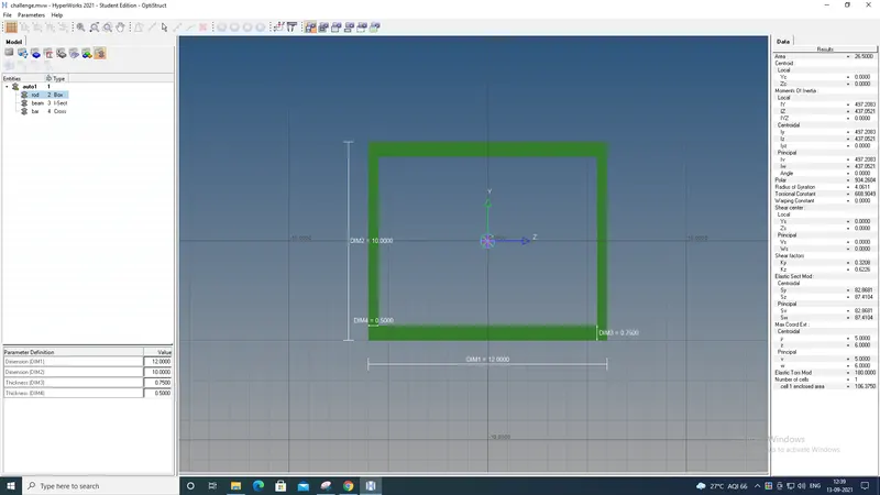
a. Rod element:- Translational DOF should be Constrained with RBE2 link
Cross-Section: BOX- Dimension a= 12 mm
dimension b=10 mm
Thickness t= 0.75 mm
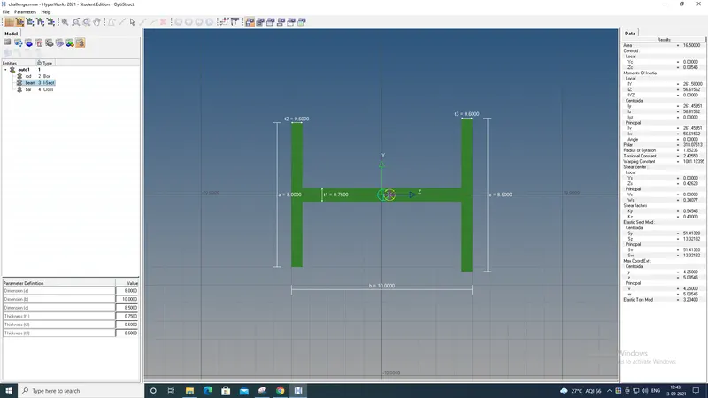
b. Beam element:- All DOF should be constrained with RBE3 link
Cross-Section: I Section- Dimension a= 8 mm
Dimension b= 10 mm
Dimension c= 8.5 mm
Thickness t1= 0.75 mm
Thickness t2= .6 mm
Thickness t3= .6 mm
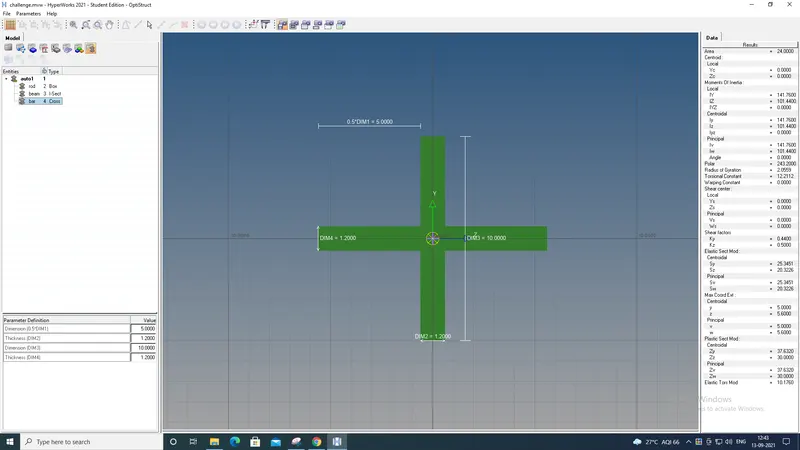
c. Bar element:- Constrain only x and y DOFs With RBE3 link
Cross-section: X section- Dimension DIM1= 5 mm
Thickness DIM2= 1.2 mm
Dimension DIM3= 10 mm
Thickness DIM4= 1.2mm
d. & e. Apply the mass of magnitude 10 with the RBE2 lin
Procedure:
Step 1: Import.
Import the geometry to workspace and then delete lines and elements present if any.
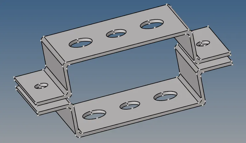
fig:Imported geometry
Step 2: Mid surface.
- Create the surface for the given two brackets.
- command: Geo>midsurface>surface>extract.
- After extracting each individual surface assign names and colour to it to differentiate them.
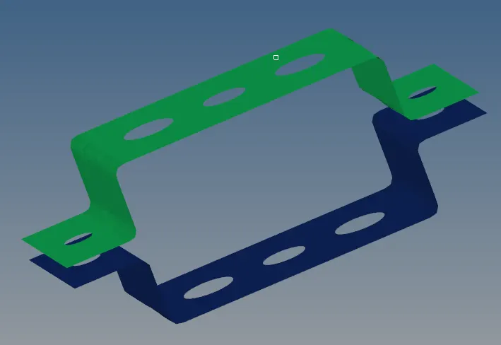
fig: Midsurface
Step 3:Mesh creation
- Create washer split with an offset of 5mm.
Geo>quick edit>washer split>offset value
2.Perform automesh.
1D>line mesh>all>type>mesh
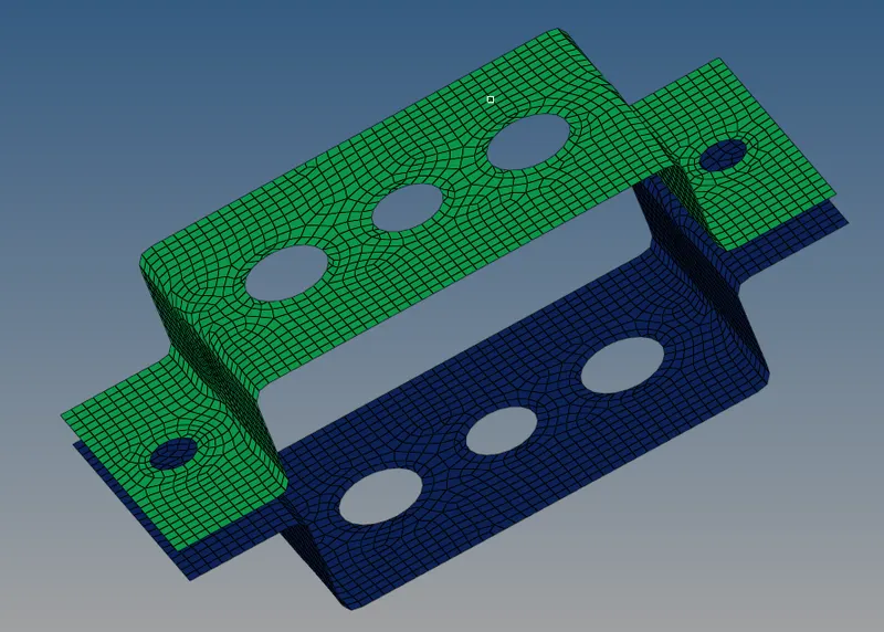
fig: Mesh creation
Step 4: Material.
Select appropriate material for the component,here the material we selected is steel.
Step 5: Create links to build elements as following,
- Rigid links at a,d and e.
- RBE3 links at b and c.
command: 1D>rigid/RBE3>nodes>DOF>create.
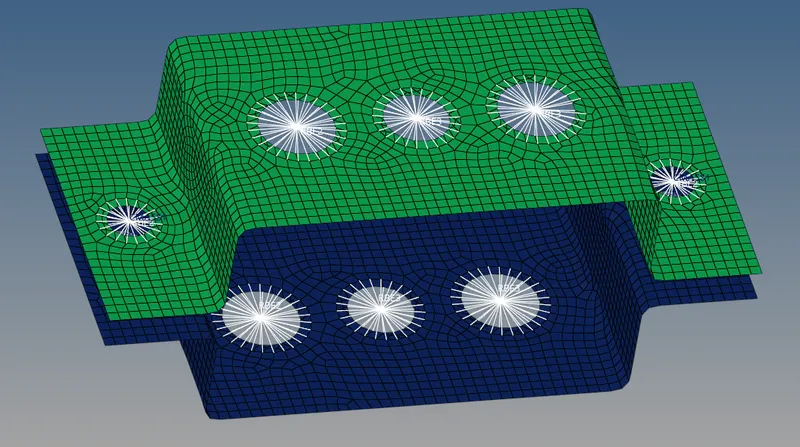
fig: Links.
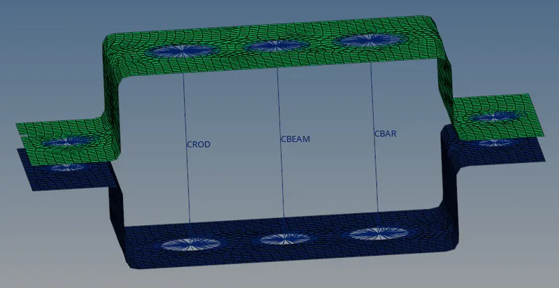
Step 6: Elements creation.
- Create the elements at appropriate links.
- Rod element at RBE2 link
- Beam and Bar elements at RBE3 links.
- command: 1D>rods/bars>nodes>property>elem type>orientation
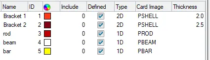
Step 7: Assigning properties.
Assign all the required properties like colour, card image, thickness for the brackets and elments present.
Step 8: 1D elements.
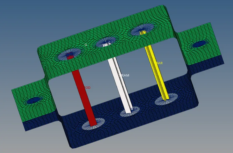
Required cross section for the elements is created using hyperbeam tool by assigning proper dimensions.
Step 9:
- Now assign these properties to the rod,bar and beam elements.
Step 10: Mass.
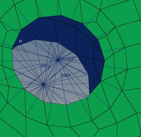
- Apply mass with magnitude 10 at d and e points.
- command: 1D>masses>mass>node>create.
Step 11:Springs
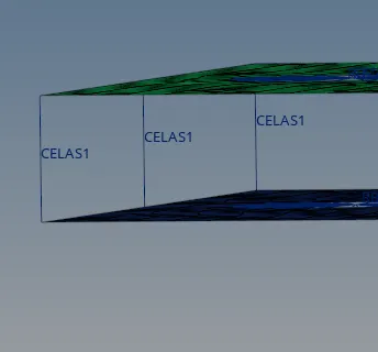
- Construct the springs at the points f.
- command: 1D>springs>nodes>create.
Conclusion:
Therefore in this challenge we have done,
- Extracting midsurface and perform meshing.
- Creating various links and elements.
- 1D element representation using hyperbeam tool.
- Assigning properties to the components
- Adding mass and constructing spring.
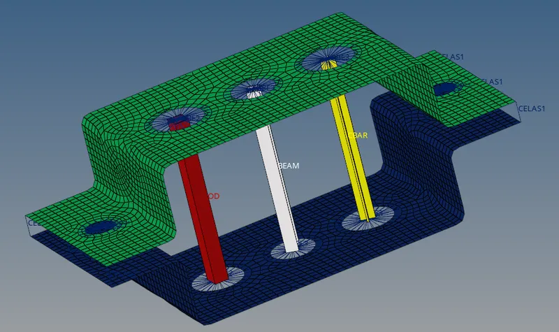
Fig: Final model after completion.