Week -2
1.AIM:
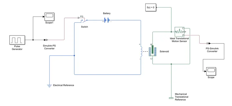
Make a Simulink model of Doorbell using solenoid block with the following details
OBJECTIVE:
To create a model where the switch is closed for 2 seconds and then released and observed the physical movements of the plunger.
DESCRIPTION:
DOOR BELL USING A SOLENOID BLOCK:
A doorbell is a signalling device placed near a door to the entrance of a building.When pressed the bell rings inside the building alerting the occupant to the presence of some one and also these may be used at different applications.Althuogh the the first door bell were mechanically operated by pulling a chord,recent one are electrically opereted by switch.
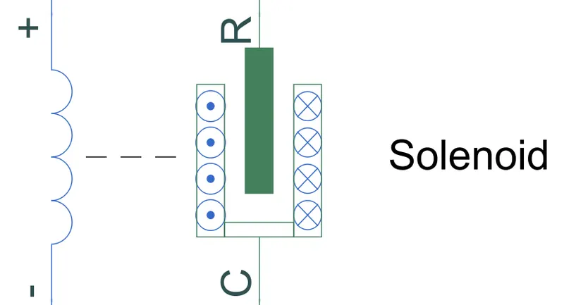
SOLENOID:
A solenoid is a device comprised of a coil of wire,the housing and a plunger.When an electric current is induced a magnetic field forms forms around the coil which draws the plunger in.Moreover a solenoid is a device which converts electrical work into mechanical work.
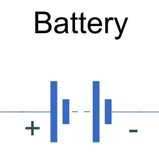
BATTERY:
A battery is a device cosisting of one or more electrical cells with external connections for powering electrical devices.When a battery is supplying electric power ,its positive terminal is the cathode and negative terminal is anode.
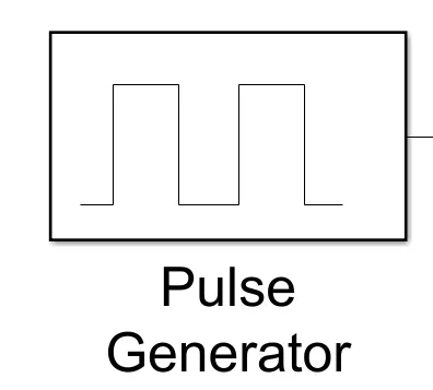
PULSE GENERATOR:
A pulse generator is an electronic circuit euipment used to generate rectangular pulses.
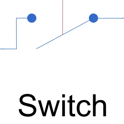
SWITCH:
Switch is an electronic component that can connect and disconnect the electric path in an electric circuit.
MODEL:
INPUT:
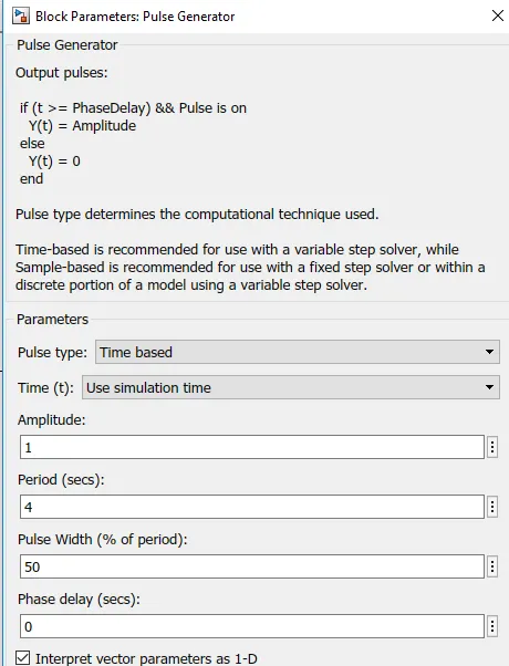
PARAMETERS : PULSE GENERATOR
GRAPH BASED ON INPUT PARAMETERS:

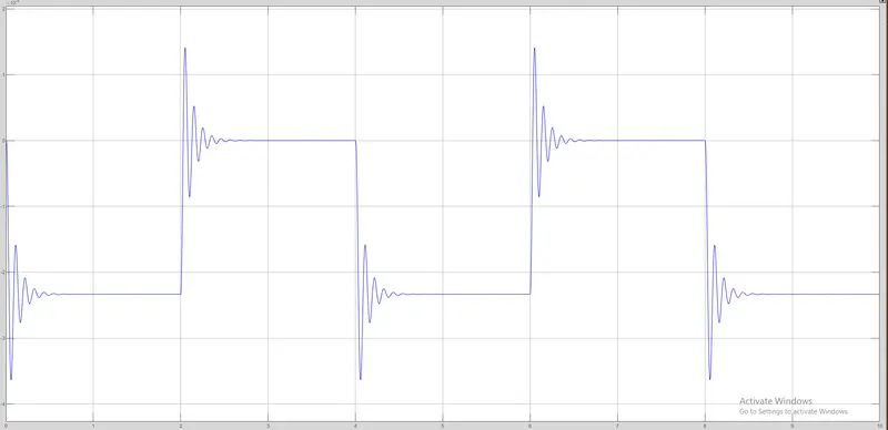
OUTPUT GRAPH:
OBSERVATIONS:
The bell oscillates for every 2 seconds.
2.
AIM:
Use a thermistor to sense the temperature of a heater & turn on or turn off the fan as per below conditions.
DESCRIPTION:
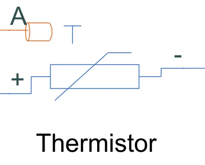
THERMISTOR:
Thermistor is a type of resistor whose resistance is reliant on temperature.
SIGNAL BUILDER:(INPUT)
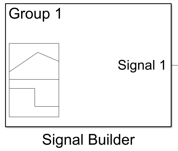
In signal builder input values are fed as per given conditions.
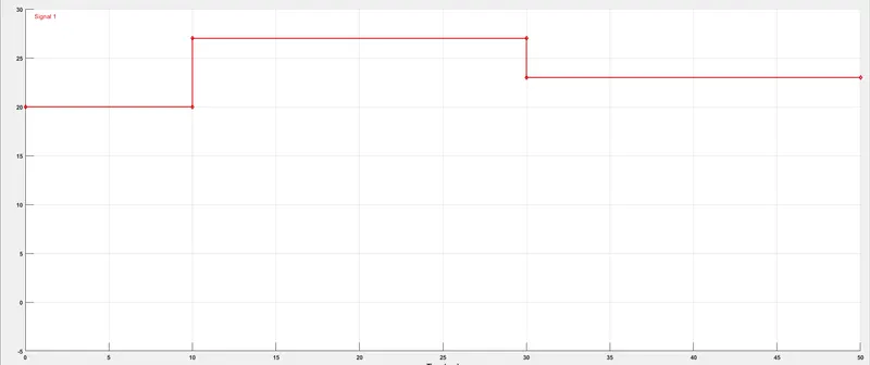
At point1-Time 0 sec-Tempertature-293K,
At point2-Time 10sec-Temperature-293K,
At point3-Time 10sec-Temperature-300K,
At point4-Time 30sec-Temperature-300K,
At point5-Time 30sec-Temperature-296K,
At point6-Time 50sec-Temperature-296K.
GRAPH:
CONTROLLED TEMPERATURE SOURCE:
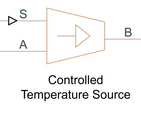
The controlled temperature source block represents an ideal source of thermal energy that is poerfull enough to maintain specified temperature difference across the source regardless of the heat flow consumed by the system.
RESISTOR:
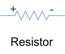
The Resistor block models a linear resistor, described with the following equation:
V =I·R
Where,
V - Voltage,
I - Current,
R - Resistance.
VOLTAGE SENSOR:
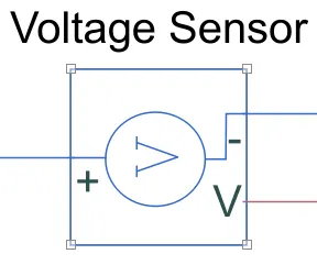
The Voltage Sensor block represents an ideal voltage sensor, that is, a device that converts voltage measured between two points of an electrical circuit into a physical signal proportional to the voltage.
ELECTRICAL REFERENCE:
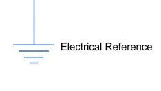
The Electrical Reference block represents an electrical ground. Electric
MODEL:
EXPLANATION OF MODEL:
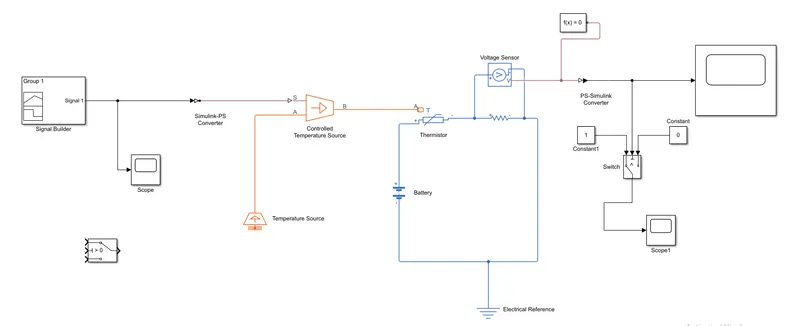
Inputs are given to the Signal Builder and Connected with Temperature Controlled Source for maintaining the specified temperature difference across the source.Then input temperature flows through thermistor.
Thermistor is connected with Resistor, ensure that thermistor connected with positive terminal of the resistor and the voltage across the resistor is given by V(+) – V(–), and the sign of the current is positive when flowing through the device from the positive to the negative terminal. This convention ensures that the power absorbed by a resistor is always positive.Connect the Positive terminal of Voltage Source to positive terminal of the thermistor and connect the negative terminal of Voltage Source to negative terminal of Voltage sensor and Resistor to get the values from the Voltage sensor(like series connection) .
Output terminal of the voltage sensor is connected with Switch.Using the Switch Parameter for giving the condition as Fan must be ON if the temperature above 25 °C, OFF otherwise. Output is Successfully executed by connecting with scope as per the given condition.
OUTPUT:
OBSEVATION:
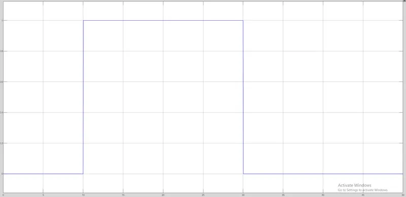
For 0-10 secs fan is in OFF condition, because temperature is 293K which is below 298K. After 10 secs temperature goes to 300K, so fan will turn ON, because temperature exceeds 298K. After 30 secs fan will turn OFF because temperature goes to 296K which is below 298K.
From the above results the given condition has been acheived and succesfully executed