Week 4.2: Project - Transient simulation of flow over a throttle body
Aim :
* To simulate transient flow simulation over a throttle body.
Objective :
* Setup a case for a transient state flow analysis over a throttle body.
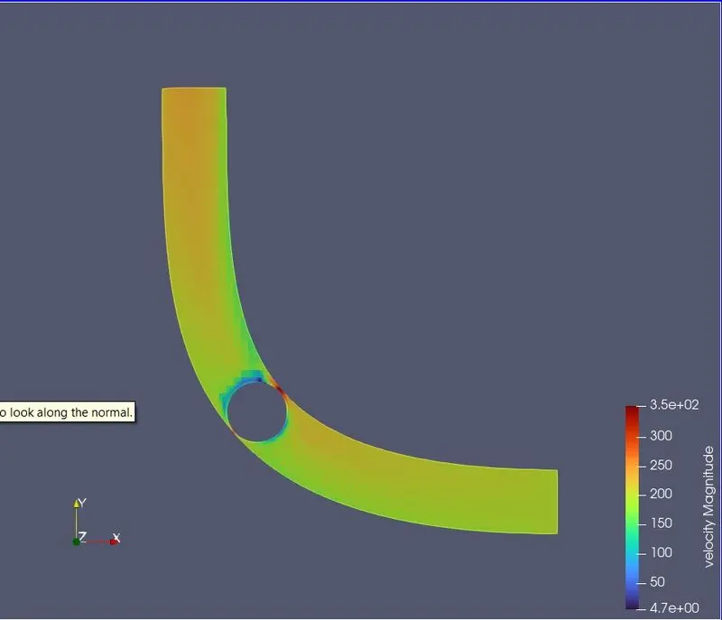
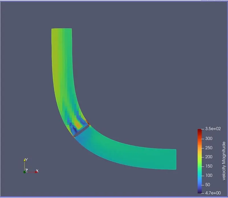
* Show velocity and pressure contour plots.
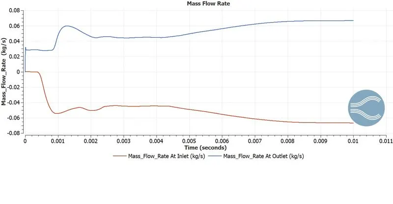
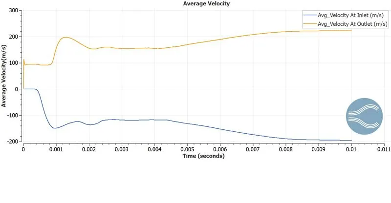
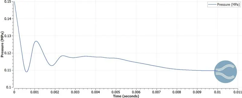
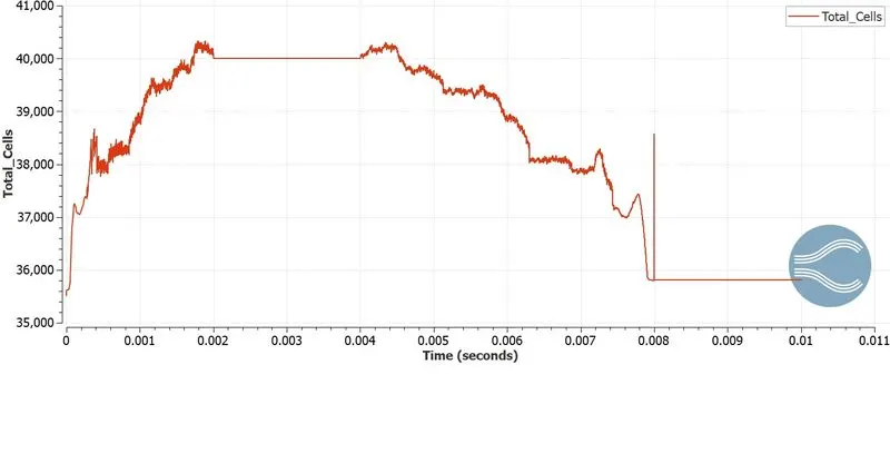
* Show plots for mass flow rate,velocity ,pressure,and total cell count & discuss results.
Introduction & Theory :
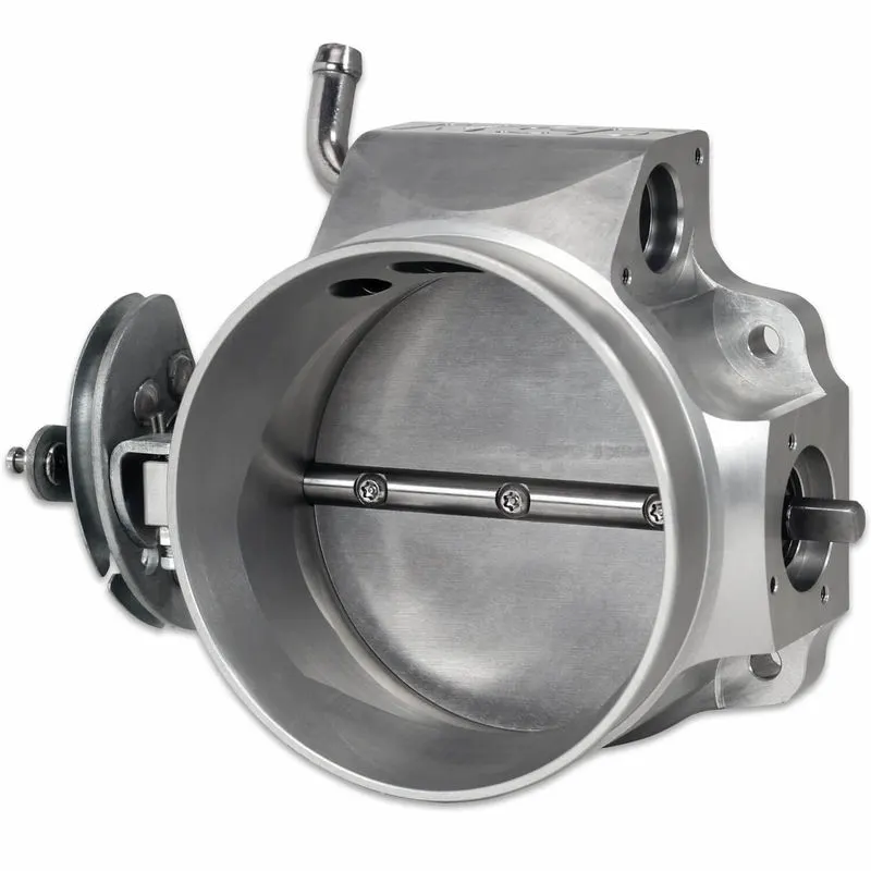
A throttle body is a tube-shaped housing that contains a flat valve (butterfly) that rotates to vary the amount of air
entering an engine.It is the mechanism by which fluid flow is managed by constriction or obstruction.
On older carbureted engines, the throttle body is built into the carburetor. It is opened and closed through a cable and
linkage from the gas pedal and engine vacuum, more fuel is delivered as the valve opens.
On a fuel-injected engine the throttle body is normally located between the air filter and the intake manifold, and is
connected to the gas pedal mechanically with a cable, or electronically by wire. When the driver presses the pedal the
butterfly in the throttle body pivots to let more air flow into the manifold.
4] Solution Procedure :
To simulate transient flow over a throttle body ,we will follow the below procedure :-
Geometry Creation --> Case Setup --> Solution --> Post Processing
4.1] Geometry Creation :
* Launch Converge and start a new project.
* Drag and drop the .stl model in converge.
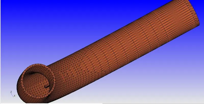
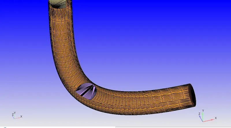
* If we observe the geometry we can see that,it has thickness.But since this is not a conjugate heat transfer analysis,we
don't need it,as it would increase the number of mesh cells.To delete thickness follow below steps,
Enable Hot Keys => Select triangle selection tool and select by angle option => select outer pipe surface => press D.
Simillarly delete other components.Also patch the open edges.
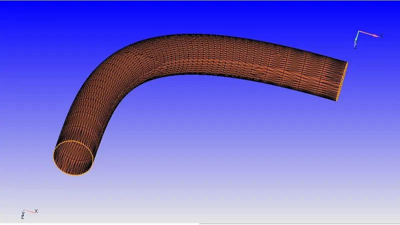
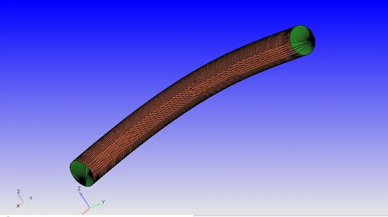
* In converge ,geometries are represented as triangles.So we need to group these triangles to create boundaries.This is the
fundamental step in Converge.
Geometery => Boundary => Flag => click on add and add 3 boundaries => rename first boundary as inlet => using by angle triangle selection,select front face triangles => apply.
* Simillarly flag outlet,elbow wall and throttle.
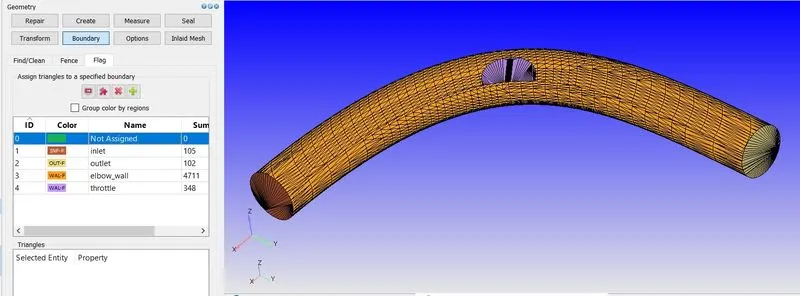
* As our flow is internal,we want all the normals to point into the fluid domain.To do that,
click on normal toggle => transform => normal => click on triangle with outside pointing normal => apply
* Make sure that geometry is clean,
Diagnosis => find => no errors.
4.2] Case Setup :
* Click on Begin Case Setup => General Flow => Done.
* Our working fluid will be air .
* Materials => Predefined mixture => Air => uncheck reaction mechanism => check species => Apply & Done.
* Keep default global transport parameters.
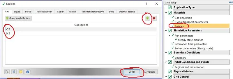
* In species add oxygen and nitrogen.
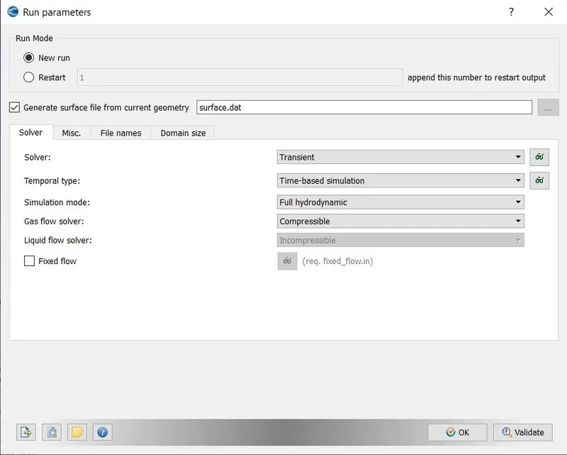
* We will be running steady state simulation.To set this follow below steps,
a] Run Parameters => Solver => select transient solver => simulation mode full hydrodynamic => Gas flow solver compressible.
*From the steady state simulation we got average velocity at outlet 186 m/s.From the geometry we can say that length of the whole elbow body is around 0.2 m.From this we can calculate the time for the flow to pass at least once through the domain which is 0.0010 sec.To get reliable results we will set simulation end time as 0.01 sec i.e. flow will pass 10 times throughout the domain.
Average Velocity = 186 m/s
Characteristics Domain Length = 0.2m
Flow Time = `0.2/186` = 0.0010 sec (Time required for flow to pass once through domain).
Time needed for 10 passes = `0.0010*10=0.01 sec`
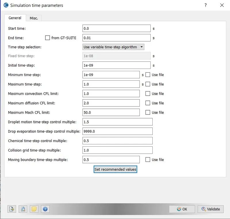
* Simulation time parameters =>
Start Time - 0 sec
End Time - 0.01 sec
Initial Time Step - 1e-9 sec.
Minimum Time Step - 1e-9 sec.
Maximum time step - 1 sec.
Maximum Convection CFL limit - 1.0.
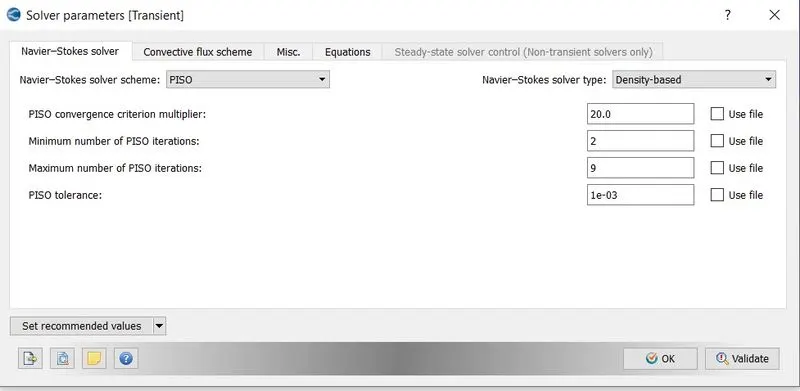
* Solver Parameters =>
Navier-Stokes solver Scheme => PISO
Navier-Stokes solver Type => Density Based
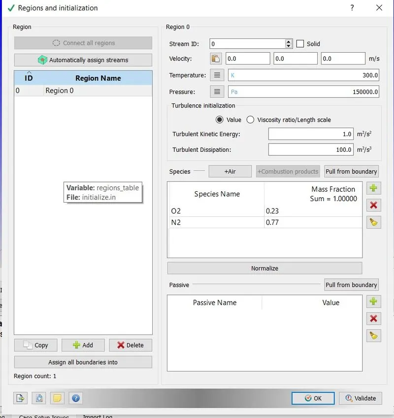
* Now before setting the boundaries,set initial region and set initial pressure and define air species.This region will be
assigned to each boundary.
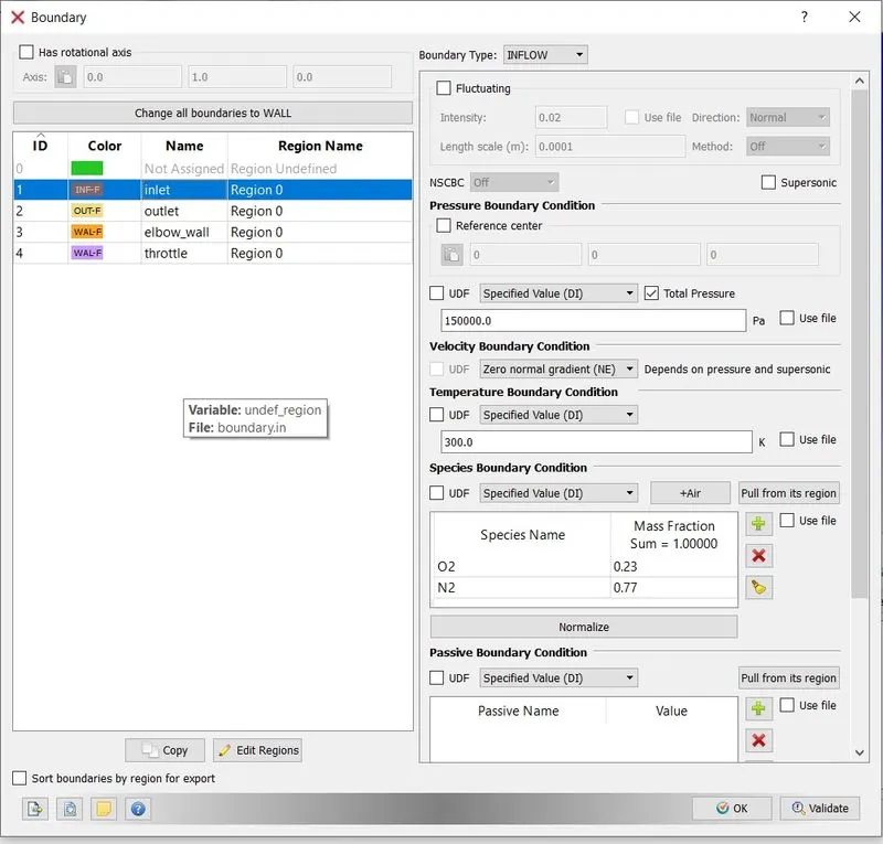
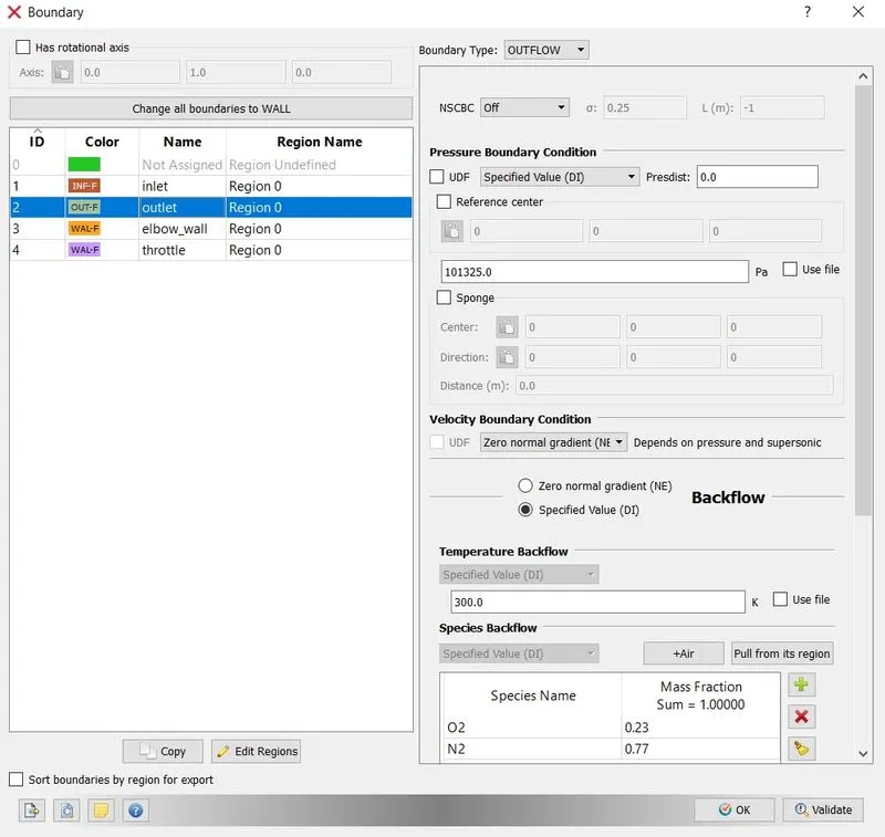
* Boundaries =>
Inlet -
Boundary Type - INFLOW
Pressure Boundary Condition - Specied value - 150000 Pa
Temperature Boundary Condition - Specied value - 300 K
Species Boundary Condition - select Air
Outlet -
Boundary Type - OUTFLOW
Pressure Boundary Condition - Specied value - 100000 Pa
Temperature Boundary Condition - Specied value - 300 K
Species Boundary Condition - select Air
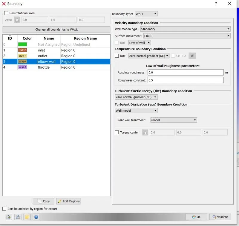
Elbow_wall -
Boundary Type - Wall
Wall Motion - Stationary
Surface Movement - Fixed
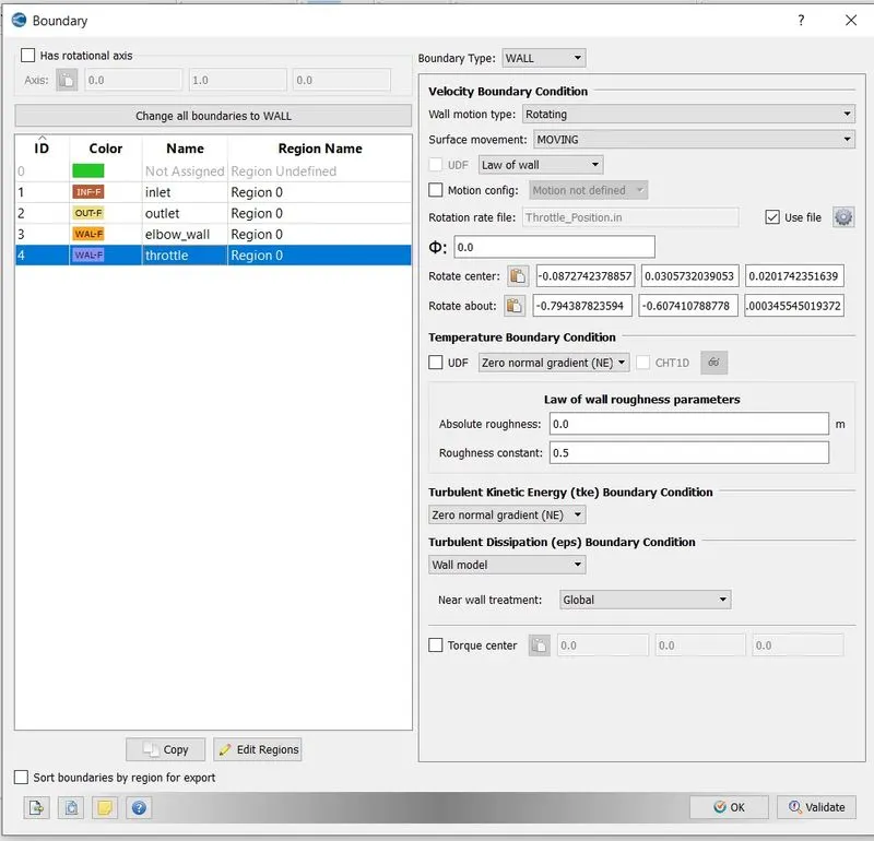
* Now we want to make sure that we rotate the throttle.For that we need rotation center and rotation axis.If we look at the geometry we can see there is a cylinder in the throttle plate.The center of this cylinder will be our rotation center. For rotation axis we will select the cell normal of the a triangle at the face of the cylinder.
* To get rotation center follow below steps,
Hide all throttle plate components except the cylinder => go to measure => select arc normal as direction => select any three vetices on the cylinder face => apply => from message log window copy arc center and paste it in rotation center.
* To get rotation axis follow below steps,
Measure => Select triangle normal as direction => select one triangle on the face of the cylinder =>from message log window copy cell normal and paste it in rotation axis.
Throttle -
Boundary Type - Wall
Wall Motion - Rotating
Surface Movement - Moving
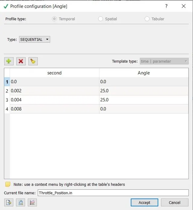
Rotation rate - 0 sec to 0.002 sec => `25 ^0`
0.002sec to 0.004 sec => `25^0`
0.004sec to 0.008sec => `0^0`
Current file name - Throttle_Position.in
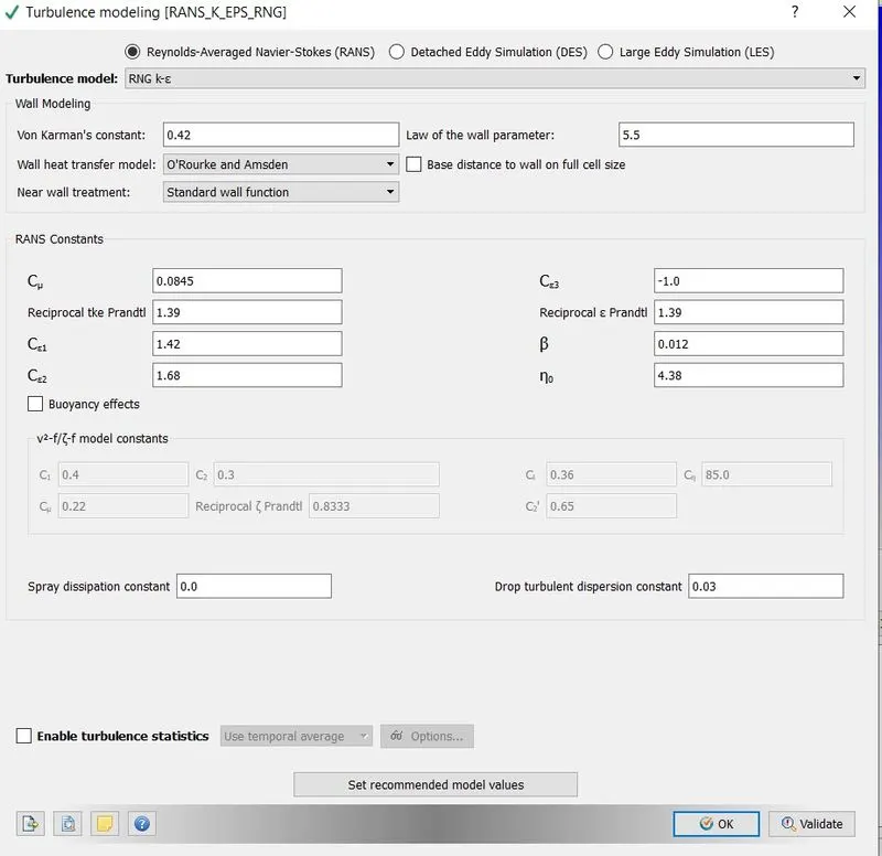
* For turbulence model select RNG k-epsilon.
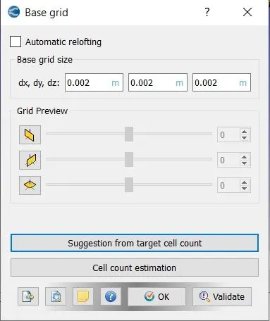
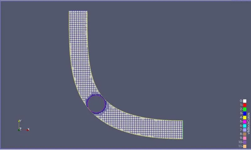
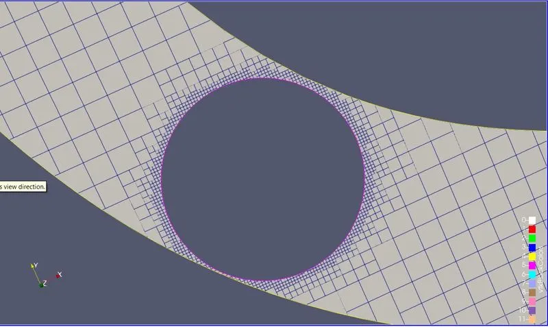
* In converge mesh generation is a fully automatic process.Converge uses cut cell method to generate the mesh.This is a patented method developed by coverge.
Base Grid = dx= 0.002 ; dy = 0.002 ; dz = 0.002 => ok
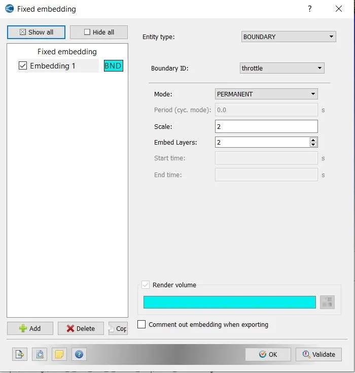
* As we want to moniter how flow behaves around the valve,we need to refine the mesh near it.To do that we will do
fixed embedding.
Boundary => Fixed Embedding => Add => Entitiy type boundary => Boundary ID throttle => Mode Permanent => Scale 2 => Embed Layers 2.
* In post variable selection,select the variables which needs to be post processed and set species mass fraction.
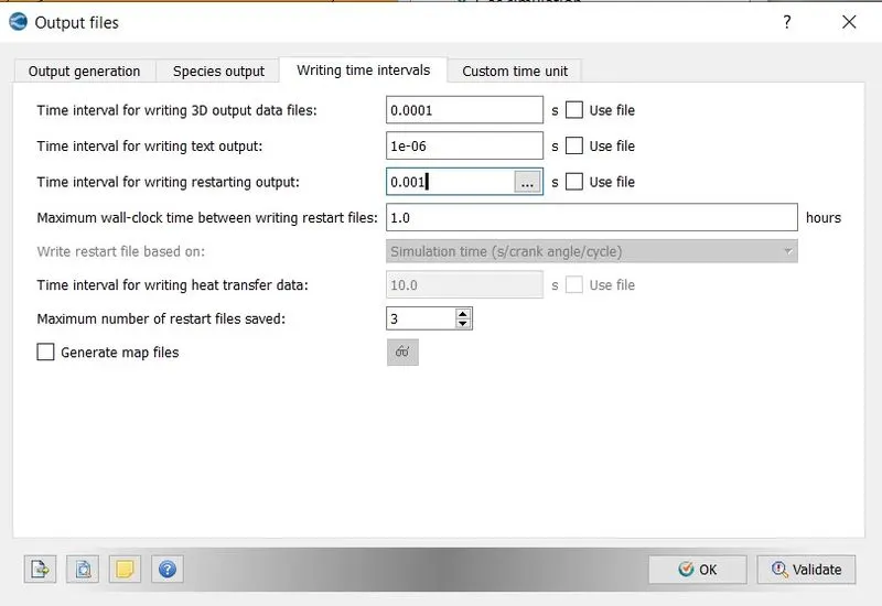
* We want our post processed graphes and animations to be smooth,so we want ample amount of ouput files.It is good practice to have at least 100 3D output files and same amount of text output files.
4.3] Solution :
* For running the simulation,first we need to export all the input files to the folder where we want to save our 3D output files,
File => Export => Export Input Files => select the desired folder => Export.
* Now we will use CYGWIN command prompt to run our simulation.But before running the simulation first we need executables which will solve the simulation,for that paste mpiexec.exe and converge.exe into the folder where we have exported all our input files.
* Now using CYGWIN command prompt,navigate to the folder where all the input files are exported,and type the below command,
mpiexec.exe -n 4 converge.exe restricted </dev/null> logfile &
* In the above command ,mpiexec.exe will help us to run our simulation in parallel,-n 4 are the number of cores on which we
want to run our simulation.As we are using the version of converge which has limit on the size of the file it can solve
hence the command restricted.And the last part of the command dump all the data that is being generated into the logfile,
which we can access during simulation procedure to see where our simulation has reached.
* The above command will create a folder named output containing all the generated 3D output data.As we will be using paraview as the postprocessing tool.Hence we need to convert these output files into the format that paraview can read.For this we will use converge post convert tool.
Go to converge post processing 3D =>give case name => select the file type => navigate to the output folder and select it
=> select all files => select all variables => convert.
This will create group file ,which will be used by paraview to post process our results.
4.4] Post-Processing :
Mesh(2 mm) Cross Sectional View
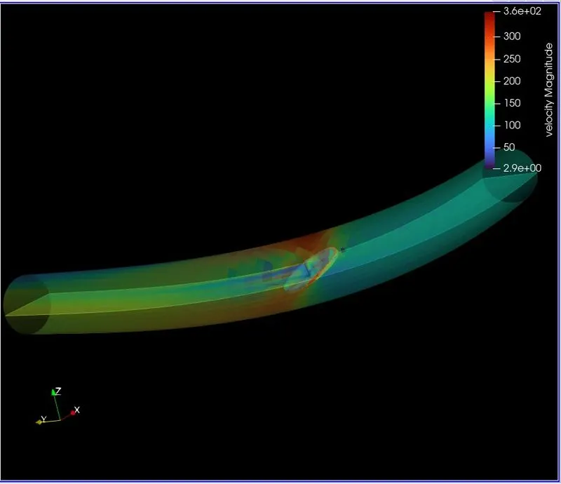
Velocity Contour (`0^0 and 25^0` valve angle)
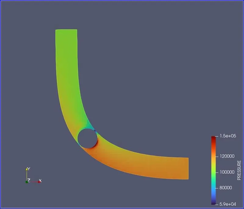
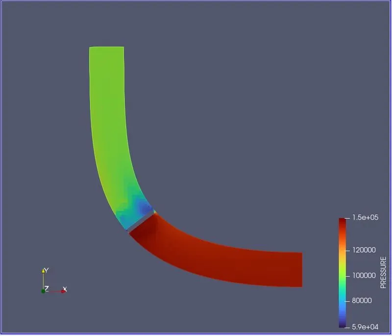
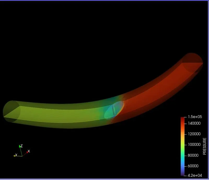
Pressure Contour(`0^0 and 25^0` valve angle)
Plot of Variables
5] Animations :
Adaptive Mesh Refinement => https://www.youtube.com/watch?v=LlKLCyc6cjc
Velocity Stremlines => https://www.youtube.com/watch?v=9y0QZ9vAak0
Velocity At Midplane =>https://www.youtube.com/watch?v=N7EkZWGrByM
Pressure At Midplane =>https://www.youtube.com/watch?v=PXBfDvj2xeo
6] Discussion :
* Both inlet and outlet mass flow rates have converged to the same value,indicating conservation of mass.The flow rate is
initially zero then there is gradual rise of flow rate between 0.001 and 0.002 sec.And towards end it decreases and increases again as throttle stops and rotates back to it's original position.
* Also we can see that mass flow rate and velocity are directely proportional to each other,which is evident from the plots.
* Pressure almost stays constant at inlet but varies drastically at outlet due to the rotation of the throttle.
* Numeber of cells reaches maximum value at maximum valve angle.
* Average velocity at outlet is 222.184m/s and maximum number of cells generated was 40226.
7]Conclusion :
* By observing above results it is clear that throttle angle affects the pressure,velocity,mass flow rate.
* As mass flow rate is conserved we can say that our results are physical.
* Hence transient flow simulation has been successfully performed on a rotating throttle body.