Week 4.2: Project Transient simulation of flow over a throttle body
Aim: Perform a Transient-state flow simulation over a throttle body inside the elbow manifold.
Introduction and Theory:
1. As Suggested, Transient-state flow simulation over throttle body has been set up in CONVERGE.
2. In this flow simulation, Air is flowing through the elbow from one to another end.
3. This elbow has a throttle plate. One end is maintained at just 1.5 bar and another at 1 bar.
4. Having this difference in pressure makes air flow from a high-pressure point to a low-pressure point.
5. In this transient state, throttle body is moving with time and returning back to original position.
The flow of a fluid is transient or unsteady if its flow parameters (i.e. velocity and pressure) are dependent not only on the position in the coordinate system used to describe the field of flow, but also on time.
Transient flow is a fluid dynamics condition where the velocity and pressure of a fluid flow change over time due to changes in system status. These changes may be caused by the starting or stopping of a pump, opening or closing of valves, or fluctuations in supply pressure from reservoirs or tanks. It is usually characterized by a powerful pressure wave or waves that may persist for a significant time after the precipitating event has ceased. Transient flow events can be extremely destructive if the magnitude and velocity of the pressure wave exceeds the capacity of the system in which it takes place. Solving recurring transient flow problems is not easy, and is generally only achievable with sophisticated software simulations.
Case Setup:
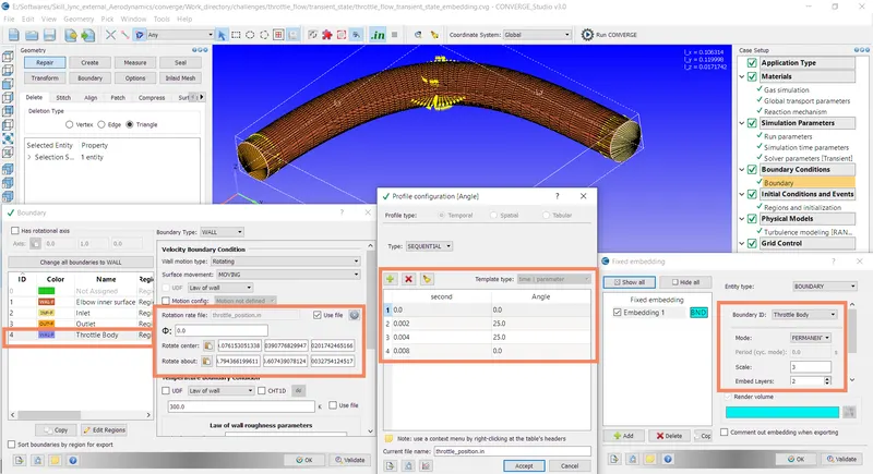
1. In converge, we are selecting a Time-based application for this project.
2. For materials, we are selecting a predefined mixture as Air which has Oxygen and nitrogen as species of this mixture.
3. In this project, the turbulence model used is RNE k-epsilon. This project was running for the maximum limit of 0.01 seconds and after every 0.001 seconds restart files and result snapshot was recorded. the maximum time step is decided based on the approximate length of the elbow body and velocity calculated at the end of steady-state simulation.
4. The solver parameters were defaulted to Navier stokes equation-based PISO solver.
5. This particular project is an example of Transient-state simulation, as throttle body is moving
with given timestamps:
0 to 2 ms- throttle moves to 25 degrees
2ms to 4 ms - stay at 25 degrees.
4ms to 8 ms - return back to 0 degrees.
6. The elbow and throttle body are assigned with different boundary conditions:
i. inlet (High-pressure point)
ii. outlet (low-pressure point)
iii. Elbow Walls (Fixed wall)
iv. Throttle Body (Rotating wall condition for transient-state simulation). For this, rotation center and axis has been defined.
7. After setting up the grid size, fixed embedding parameters; variables for post-processing were selected. (velocity, mass flow, pressure, density, temperature)
8. After exporting input files, using CYGWIN (command prompt) was used to simulate the project setup.
9. Output files were later converted using CONVERGE studio for post-processing in ParaView.
10. Maximum CFL limit is set at 1.00
11. base grid size is 0.002 m.
12. The bounding box dimensions are as follows:
Ix= 0.106314 m
Iy= 0.119998 m
Iz= 0.0171742 m
Summary of Results:
Here are the results of this simulation,
| Pressure Contour | 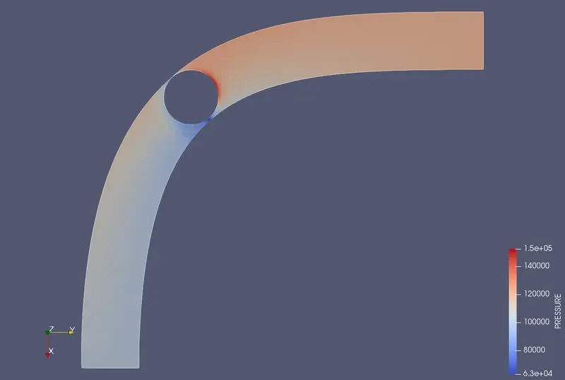 |
| Velocity Contour | 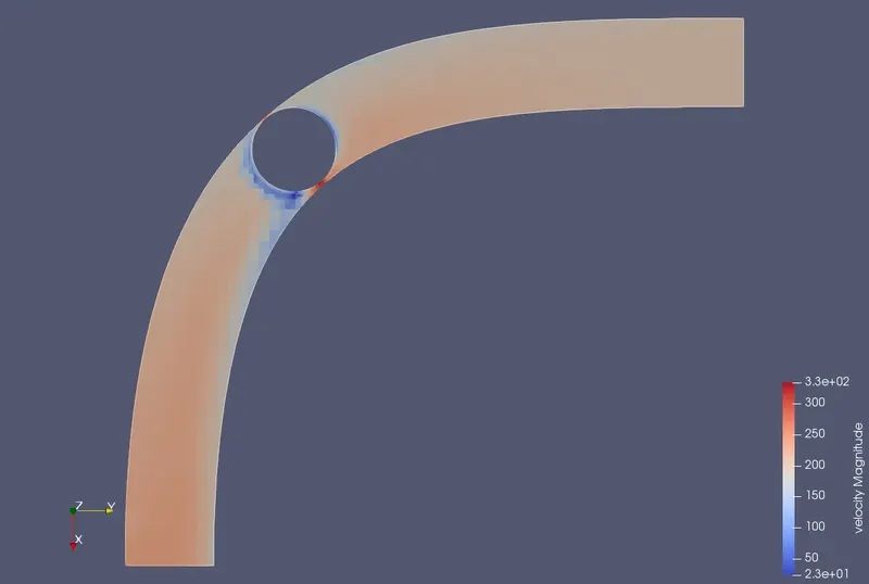 |
| Flow Direction Glyph | 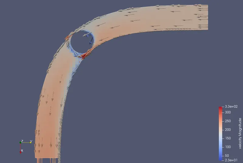 |
| Mesh | 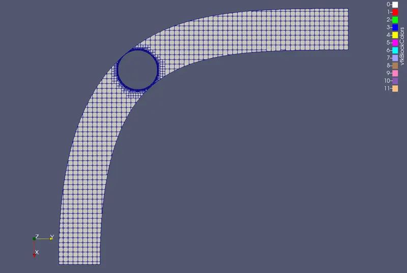 |
| Outlet Pressure Plot | 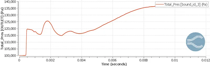 |
| Velocity Plot | 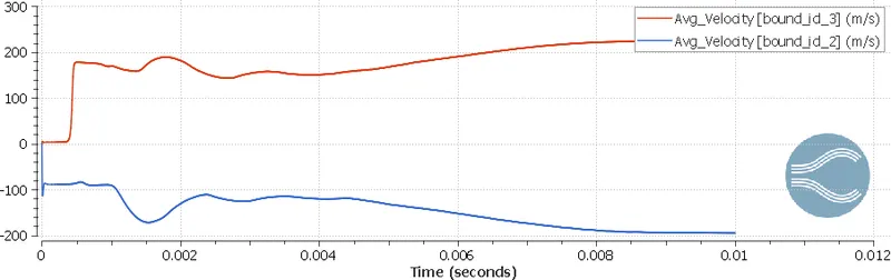 |
| Inlet Mass flow rate | 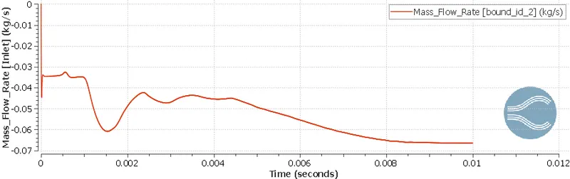 |
| Outlet Mass Flow Rate | 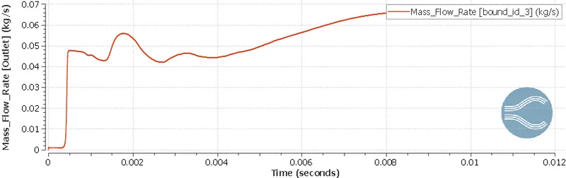 |
| Total Cell count | 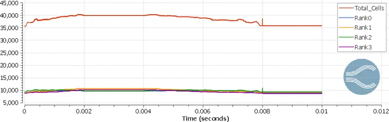 |
1. Total cell counts (no. of elements) in this simulation were ranging from 35500 to 40500 as the throttle body is moving according to the timestep mentioned above. Also, for a better understanding of flow patterns over the throttle body, we added local refinement. In other terms, we added embedding to just near the throttle body.
2. Near the throttle body, when air is hitting the body, pressure is increasing due to flow resistance. And as air is leaving the trailing part of the throttle body, pressure is decreasing.
Animation:
Conclusion:
Transient-state flow simulation with fixed embedding mesh configurations has been analyzed and plots, contours have been obtained using ParaView.