Week 4.2: Project - Transient simulation of flow over a throttle body
AIM
To simulate the flow over a throttle body in converge
OBJECTIVES
- Set up and run the transient state simulation for flow over throttle body.
- Post process the results and show pressure and velocity contours.
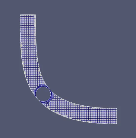
- Show the mesh (i.e surface with edges)
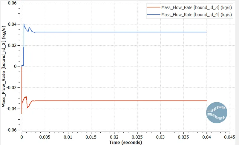
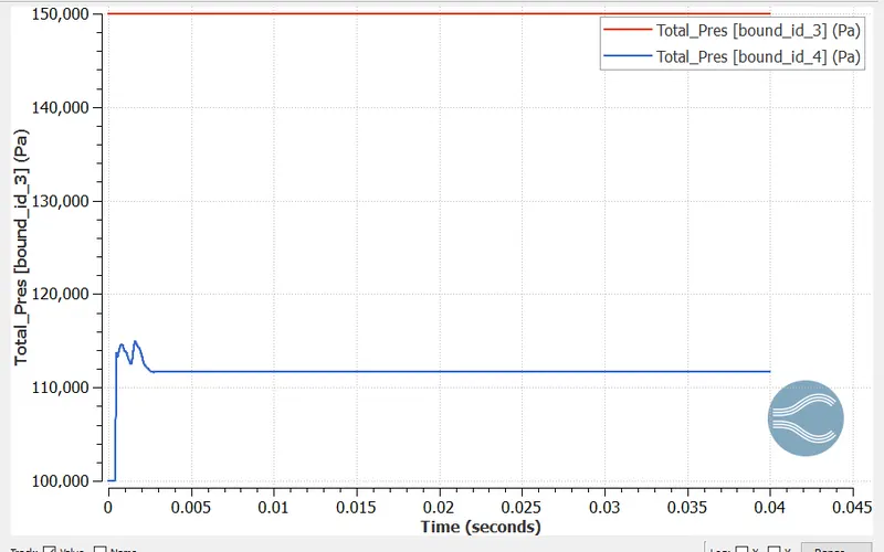
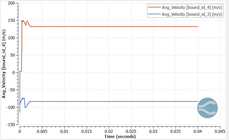
- Show the plots for pressure, velocity, mass flow rate and total cell count.
THEORY
Butterfly valve
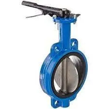
A butterfly valve is a valve that isolates or regulates the flow of a fluid. The closing mechanism is a disk that rotates. Operation is similar to that of a ball valve, which allows for quick shut off. Butterfly valves are generally favored because they cost less than other valve designs, and are lighter weight so they need less support. The disc is positioned in the center of the pipe. A rod passes through the disc to an actuator on the outside of the valve. Rotating the actuator turns the disc either parallel or perpendicular to the flow. Unlike a ball valve, the disc is always present within the flow, so it induces a pressure drop, even when open. A butterfly valve is from a family of valves called quarter-turn valves. In operation, the valve is fully open or closed when the disc is rotated a quarter turn. The "butterfly" is a metal disc mounted on a rod. When the valve is closed, the disc is turned so that it completely blocks off the passageway. When the valve is fully open, the disc is rotated a quarter turn so that it allows an almost unrestricted passage of the fluid. The valve may also be opened incrementally to throttle flow.
Effect of flow near constriction
When flowing through a constricted area of a pipe, a fluid's velocity increases and its static pressure decreases. This principle is known as the Venturi effect. The resistance to flow causes a drop in pressure as you proceed along the tube. When a positive pressure is applied to a tube with a constriction, the pressure in the constriction is lowered compared to that in the larger tube.
Venturi effect
The Venturi effect is the reduction in fluid pressure that results when a fluid flows through a constricted section (or choke) of a pipe. In inviscid fluid dynamics, an incompressible fluid's velocity must increase as it passes through a constriction in accord with the principle of mass continuity, while its static pressure must decrease in accord with the principle of conservation of mechanical energy (Bernoulli's principle). Thus, any gain in kinetic energy a fluid may attain by its increased velocity through a constriction is balanced by a drop in pressure.
SIMULATION PROCEDURE
- Setting up the case in converge
- Running the simulation in cygwin
- Post convert using cygwin/converge
- Post processing in paraview
The first step is case setup in converge. Open converge and then import the geometry.
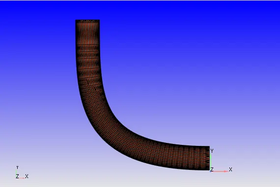
Go to boundary and create boundary fences as shown below
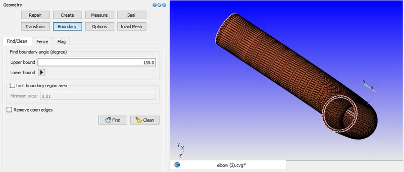
In this geometry there is a thickness to the elbow, which is not needed. So delete the outer pipe and its thickness.
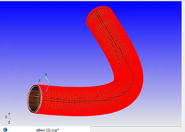
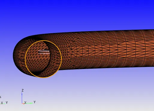
Patch the open edges.
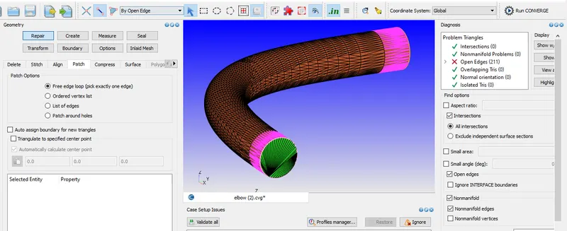
The next step is boundary flagging. Name the boundaries.
The orientation of normals should be checked such that it should be pointing inwards.
Then run a diagnosis check to find if there are any errors.
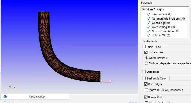
Geometry preparation is completed. The next step is case setup.
Inorder to run a transient state simulation firstly under application type in the setup tree, a time based simulation must be selected.
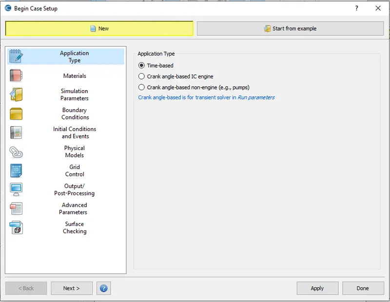
In materials turn on species and in predefined mixtures select air.
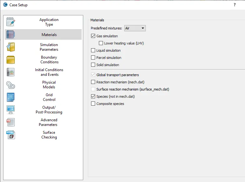
Choose the default properties in the gas simulation. In global transport parameters the default parameters are retained. In species tab, add O2 and N2.
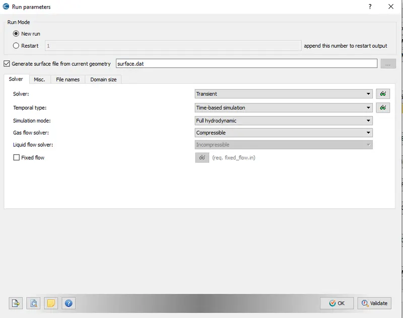
The next one in the case setup tree is the simulation parameters. Next in the run parameters tab, select transient solver.
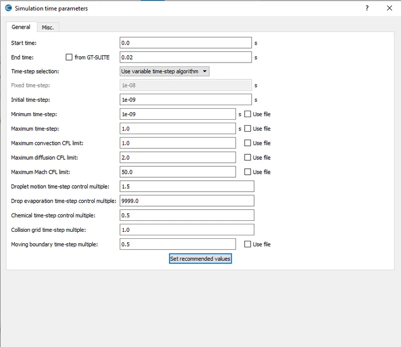
Set the simulation time parameters
Solver parameters:
Solver scheme - PISO
Solver type - density based
Pressure preconditioner - none
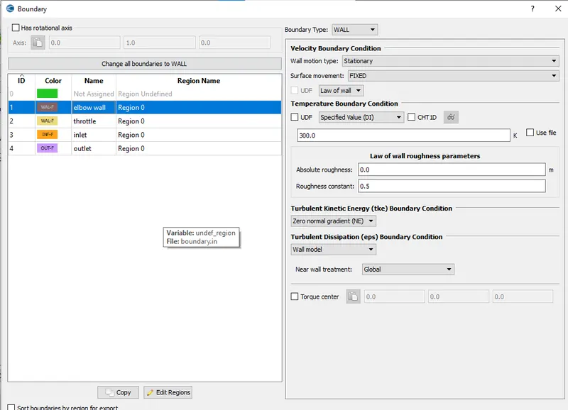
Give the boundary conditions as given below.
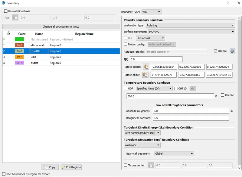
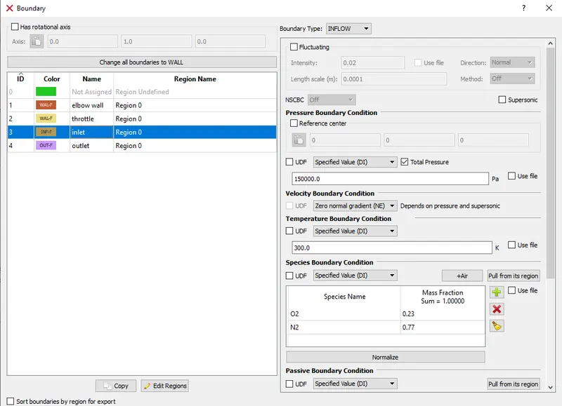
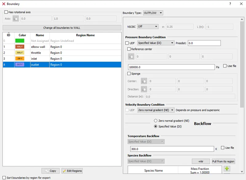
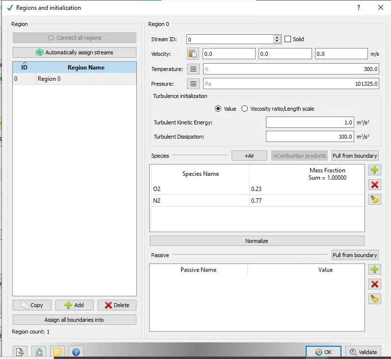
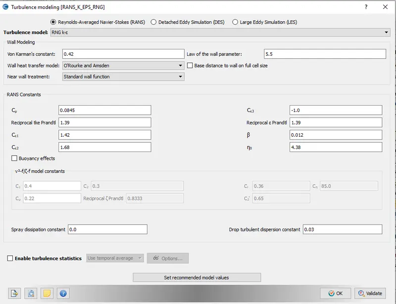
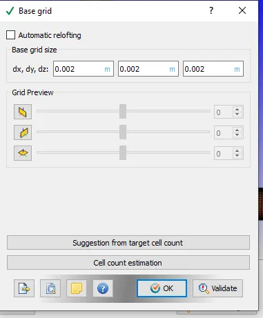
In grid control turn on fixed embedding. In base grid tab, the mesh sizes is to be entered.
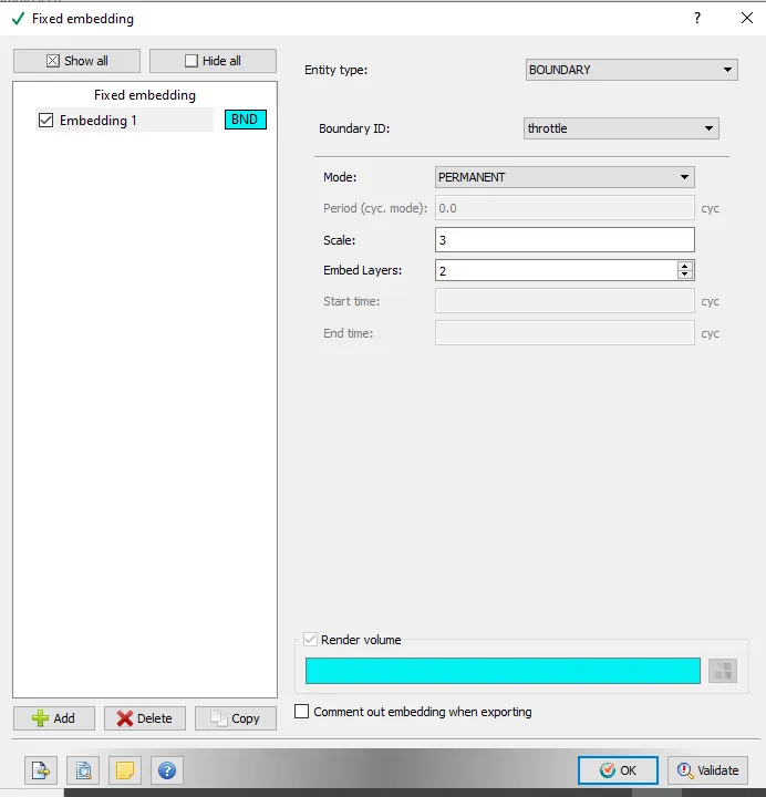
The next step is to provide fixed embedding. Fixed embedding is used to refine the mesh to a value that is lower than the prevalent base size. This is especially useful if we are looking to refine near wall to capture the boundary layer or the wake of a body more accurately. Here fixed embedding is done in throttle boundary with an embedding scale of three.
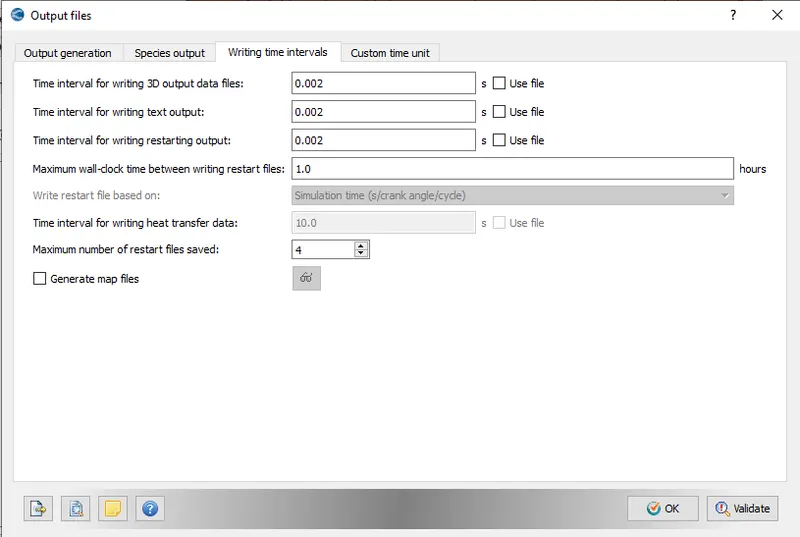
Set the frequency of generation of output files.
Once the case setup is completed, export the input files into a required directory. Then launch cygwin and navigate to the directory through CYGWIN in which all input files has been exported and then enter the command to run the simulation ' mpiexec.exe -n 1 converge.exe restricted'. After that post convert using converge and post process the results in paraview.
RESULTS
Mesh
Mass flow rate
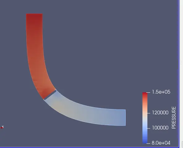
Pressure plot
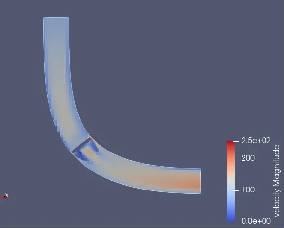
Velocity plot
Total cell count
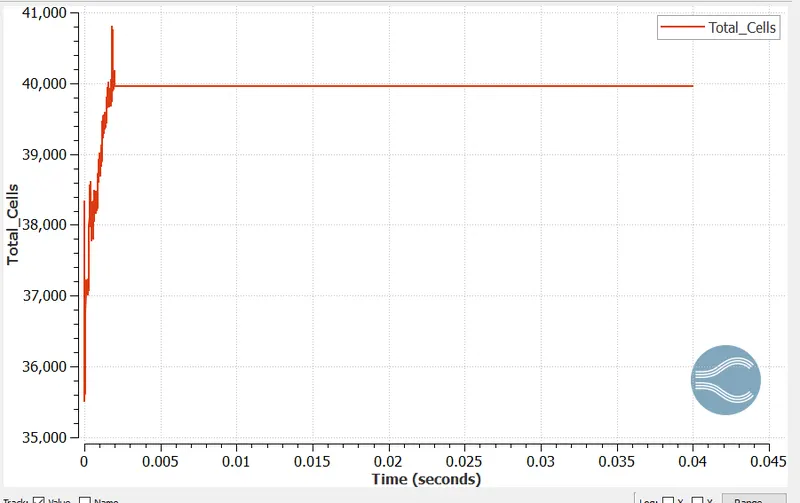
There is a rapid increase in the cell count upto 0.002 seconds. This is due to the valve movement.
Pressure contour
Velocity contour
Calculation of end time for the simulation:
Flow through time = characteristic length / velocity
= 0.11/80 = 0.0013 = 0.002 approx.
Velocity animation is provided in the below link:
https://drive.google.com/file/d/1rU3MTbqozGGFbGfQONcfamqe1Emqvrc8/view?usp=sharing
CONCLUSION
Transient state simulation for flow over a throttle body was studied. Movement of the throttle impacts the pressure and velocity in the region near to the valve.