Week 4.2: Project Transient simulation of flow over a throttle body
PROJECT TRANSIENT SIMULATION OF FLOW OVER A THROTTLE BODY
AIM: To run the simulation of a Transient simulation of flow over a throttle body.
OBJECTIVE:
- Post-process the results and show pressure and velocity contours.
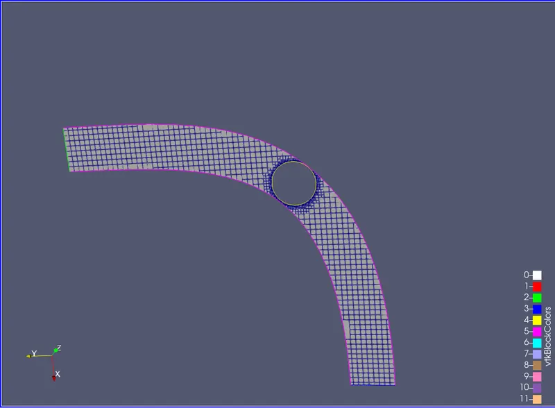
- Show the mesh (i.e surface with edges)
- Show the plots for pressure, velocity, mass flow rate, and total cell count.
- Create an animation in which its throttle movement should be visible.
- Upload an animation on Youtube and provide the Youtube link for animation in your report.
THEORY:
A throttle is a mechanism by which fluid flow is managed by constriction or obstruction.
An engine's power can be increased or decreased by the restriction of inlet gases (by the use of a throttle), but usually decreased. The term throttle has come to refer, informally, to any mechanism by which the power or speed of an engine is regulated, such as a car's accelerator pedal. What has often been termed a throttle (in an aviation context) is also called a thrust lever, particularly for jet engine-powered aircraft? For a steam locomotive, the valve which controls the steam is known as the regulator.
SETUP AND SOLUTION:
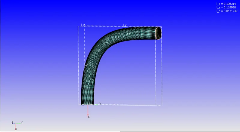
Geometry:
Mesh:
Setup:
|
Application Type |
Time-based |
|
MATERIALS: |
|
|
1. Gas simulation |
Standard |
|
2. Global Transport Parameters |
Standard |
|
3. Reaction Mechanism |
Standard |
|
SOLUTION PARAMETERS |
|
|
1. Run Parameters Steady-state monitor: |
Transient no hydrodynamic solver>Full hydrodynamic>Compressible |
|
2. Simulation time parameters |
|
|
3. Solver parameters |
Navis-stokes solver scheme: PICO Navis-stokes solver type: pressure-based
|
|
BOUNDARY CONDITIONS |
|
|
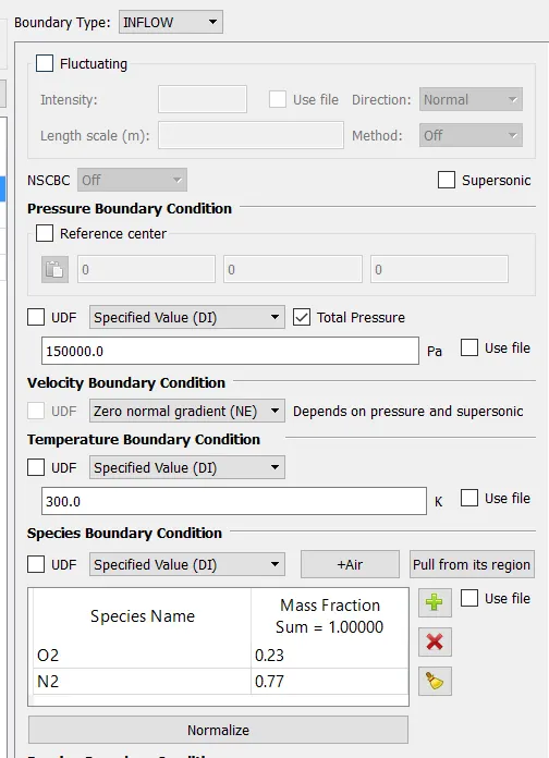
1. Inlet |
 |
|
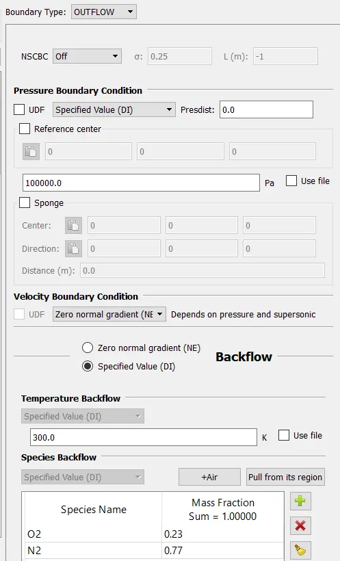
2. Outlet |
 |
|
3. Elbow-wall |
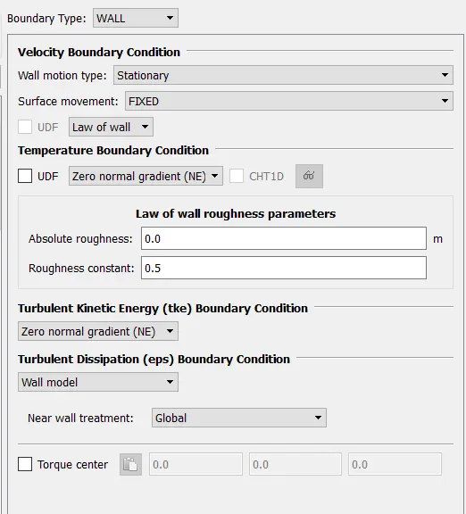 |
|
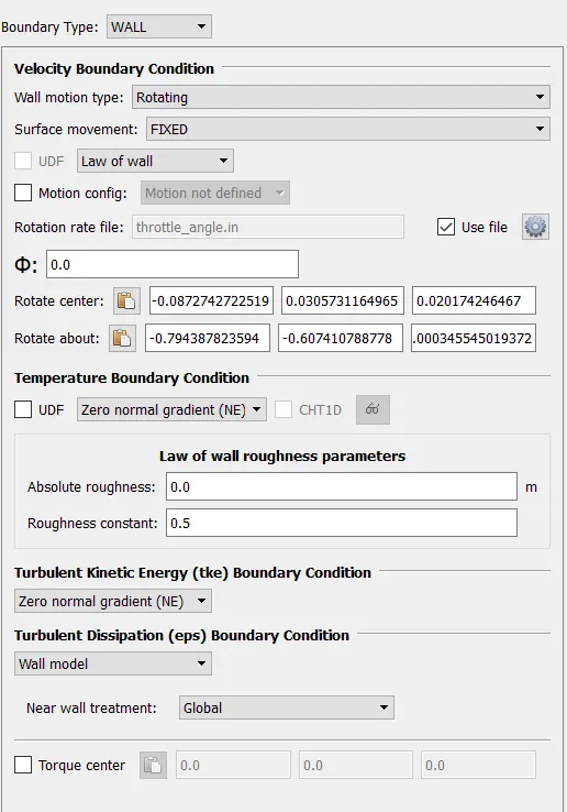
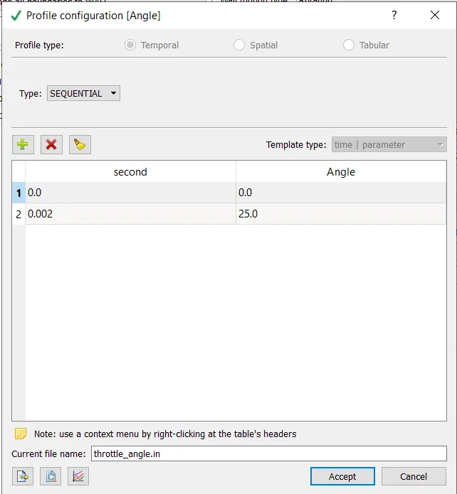
4. Throttle |
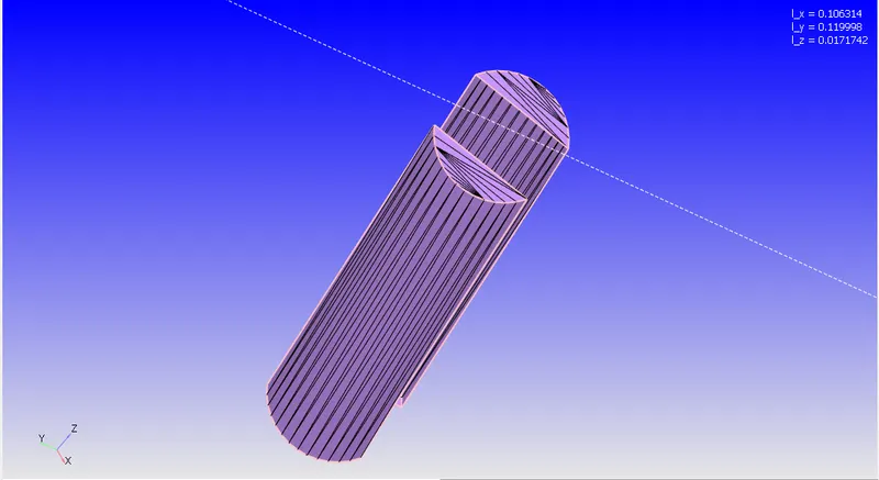
From this part of the throttle, we measure the arc radius or by triangle normal to know the angle of rotation
File created for the rotation of the throttle in the required direction.
|
|
INITIAL CONDITIONS AND EVENTS |
|
|
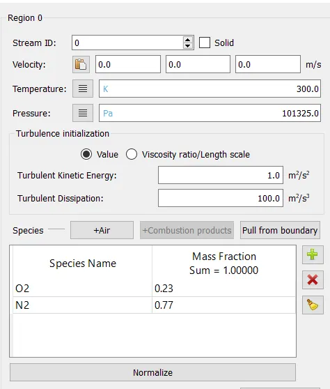
1. Regions and initialization |
|
|
PHYSICAL MODELS |
RNG- k-epsilon |
|
GRID CONTROL |
|
|
1. Base mesh |
dx = 2e-3m, dy = 2e-3m and dz = 2e-3m |
|
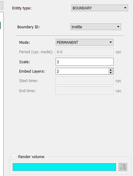
2. Fixed embedding |
|
|
OUTPUT/POST-PROCESSING |
|
|
1. Post variable selection |
Standard |
|
2. Output files: |
|
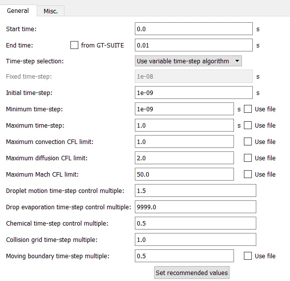
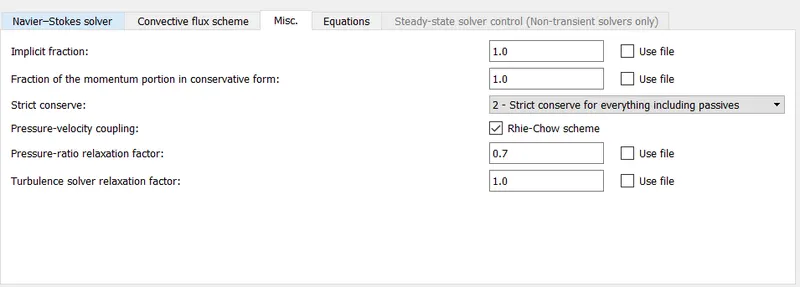
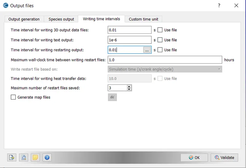
Then Export the Files
Then continuing the setup in Cygwin :
- leading to the folder where the exported files are saved
- Then using mpiexec.exe -n 2 converge.exe restricted to simulate the setup
- After the output is generated, we lead the Cygwin to the output folder, and by copying the post_convert folder and
- Using mpiexec.exe -n 2 post_convert.exe and converting these files for processable output in ParaView.
Solution:
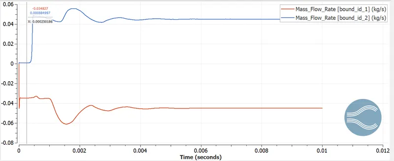
Mass flow rate plot:
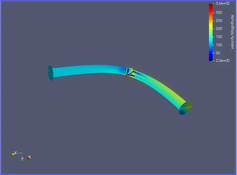
Velocity counter:
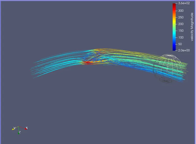
Velocity streamline:
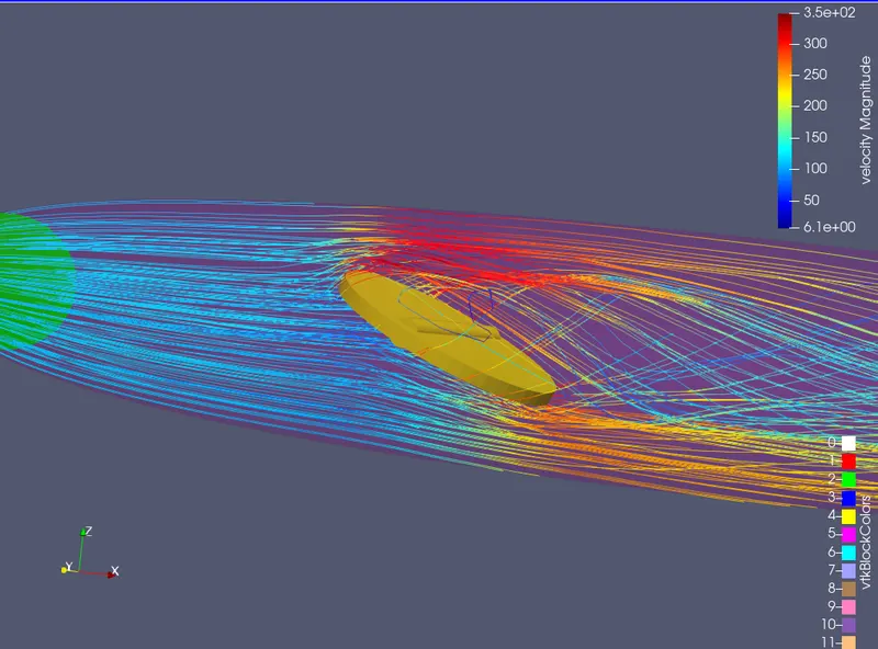
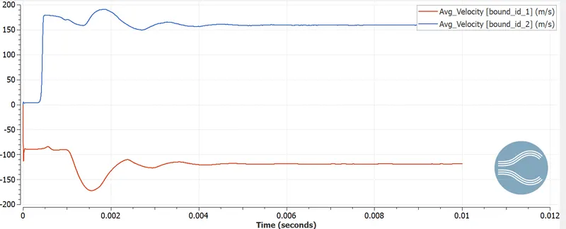
Velocity plot:
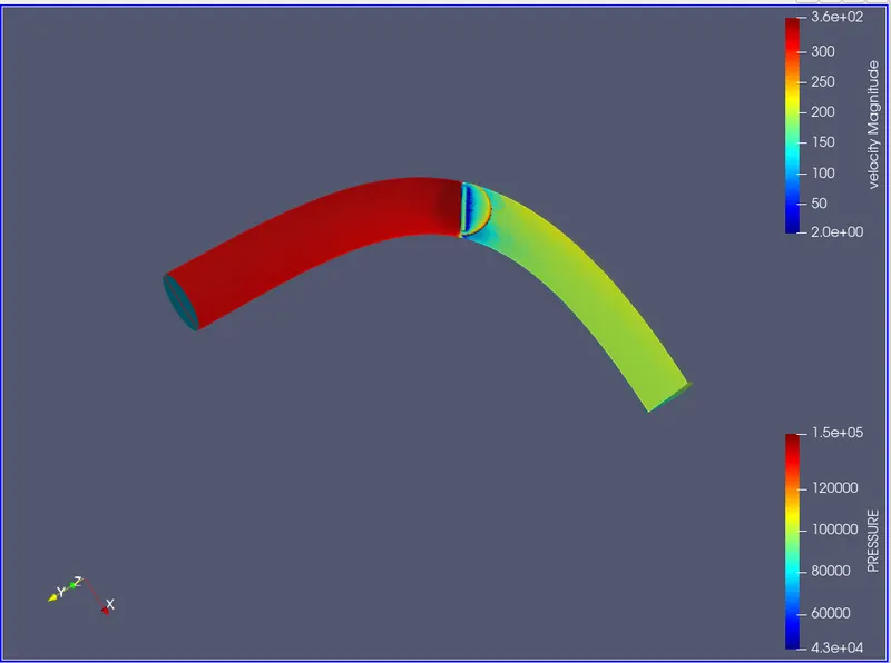
Pressure counter:
Pressure Plot:
Total pressure
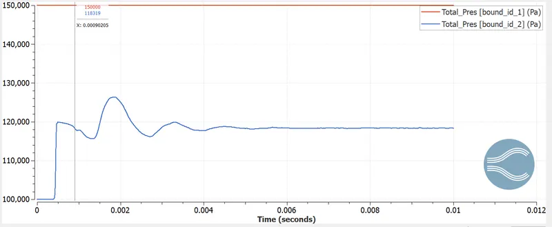
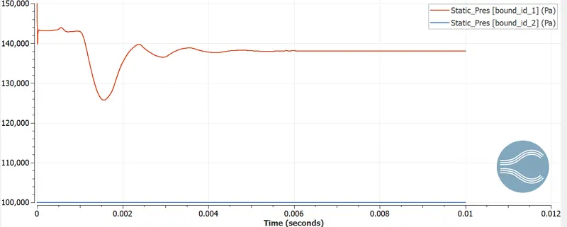
Static Pressure:
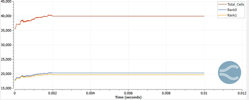
Total Cell Count:
Animation:
Velocity:
Pressure:
CONCLUSION:
-
As the Throttle body rotates there is an obstruction in the flow of fluid and hence its velocity and hence kinetic energy of the fluid is converted into pressure energy therefore Total Pressure increases.
-
Due to the rotation of the throttle plate, the wake region is formed on the plate causing deceleration of flow leads to separation of flow hence a decrease in static pressure at the outlet.
-
Rotation of Throttle plate causing obstruction to the fluid flow increases the pressure gradient(pressure force in the direction of flow) forced fluid hence the velocity of fluid flow increase therefore Mass flow rate increases at the outlet.
-
Through contour plots for velocity and pressure, it is observed that the movement of the throttle impacts the velocity and pressure in the region rear to the throttle valve. Also, the movement of the throttle has an impact on the cell count until 2 milliseconds.