Week 4-1D Element Creation Challenge
Mesh the Given component with the Size of 5 Units. Create 1D elements on the following component with given cross-section and DOF
Procedure:
- Creating mid surface on the given model
- Import model from geometry (IGES file)
- Create mid-surface on given model
[geometry->midsurfaces->autoectraction]
- Remove the surface(make invisible)just keep the mid surfaces
- Make offset value 5 in holes on the model
[geometry->quick edit->washersplit->offsetvalue(5)]
- Mesh the mid surface with size of 5 units
[2D-automesh-automesh-element size(5)]
- Adjust the no of nodes in holes for better structure of mesh
- Rod element:- Translational DOF should be Constrained with RBE2 link
given data: Cross-Section: BOX- Dimension a= 12 mm
dimension b=10 mm
Thickness t= 0.75 mm
Procedure:
- create rbe2with only dof only on translational direction
(only in dof1,2,3)[nodes-calculatenode-bypath]
- by creating rbe2 elements in 2 holes in model connect it with a rod element by creating nodes on both rbe2 link
[1D-rod-nodes]
- create box element with given size
[1D-hyperbeam-standardsection- hyperbeam-thin walled box] and give the dimension as per given
- create property for rod element and assign the property
- set card image into PROD
- set beam section to given dimensions
- assign the property and set into 2D view
- Beam element:- All DOF should be constrained with RBE3 link
Cross-Section: I Section- Dimension a= 8 mm
Dimension b= 10 mm
Dimension c= 8.5 mm
Thickness t1= 0.75 mm
Thickness t2= .6 mm
Thickness t3= .6 mm
Procedure
- create RBE3 link in all DOF
[1D-RBE3-calculate node-by path]
- create beam element by connecting the RBE3 elements
[1D-beam-nodes-create]
- create the I section in given dimension
[1D-hyperbeam-standardsection- hyperbeam- I section]
- create a property for beam element
- set card image PBEAM
- set beam section into given section
- assign all property and set into 2D view
- Bar element:- Constrain only x and y DOFs With RBE3 link
Cross-section: X section- Dimension DIM1= 5 mm
Thickness DIM2= 1.2 mm
Dimension DIM3= 10 mm
Thickness DIM4= 1.2mm
procedure
- create RBE3 link in all DOF
[1D-RBE3-calculate node-by path]
- create bar element by connecting the RBE3 elements
[1D-beam-nodes-create]
- create the x section in given dimension
[1D-hyperbeam-standardsection- optistruct- cross section]
- create a property for bar element
- set card image PBAR
- set beam section into given section
- assign all property and set into 2D view
- & e. Apply the massof magnitude 10 with the RBE2 link
Procedure
- create RBE2 link in all DOF
[1D-RBE3-calculate node-by path]
- create a mass of magnitude =10 in each RBE2 link
- Join the two components with Spring elements
Procedure
Create a spring element in both edges
[1D-spring-node-create]
Conclusion
- Mesh the Given component with the Size of 5 Units. Create 1D elements on the following component with given cross-section and DOF
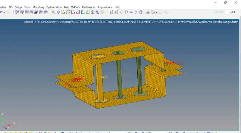
Fig: Isometric view
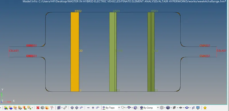
FIG: Front view
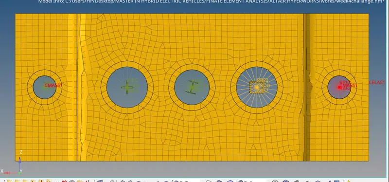
Fig: top view