Challenge

Week 4-1D Element Creation Challenge

AIM:- To create a 1D element with the help of Hyperworks.

OBJECTIVES:-

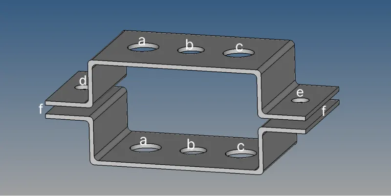
Mesh the Given component with the Size of 5 Units. Create 1D elements on the following component with given cross-section and DOF

a. Rod element:- Translational DOF should be Constrained with RBE2 link

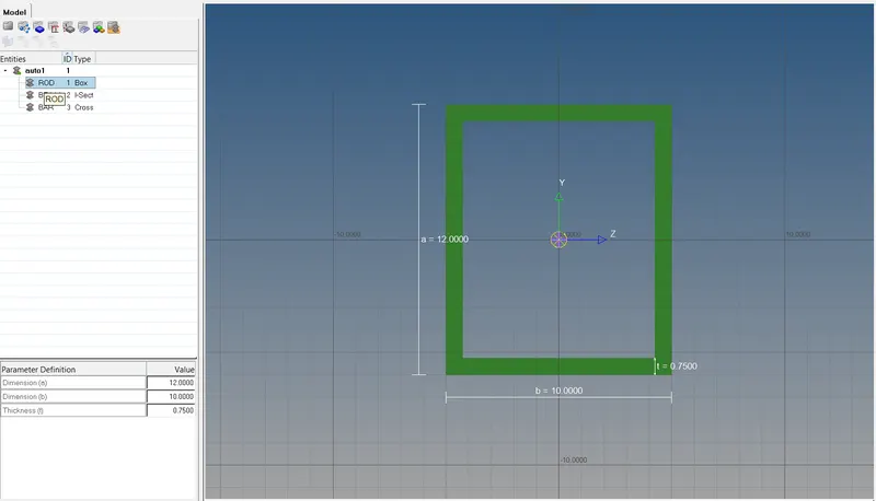
Cross-Section: BOX- Dimension a= 12 mm

dimension b=10 mm

Thickness t= 0.75 mm

b. Beam element:- All DOF should be constrained with RBE3 link

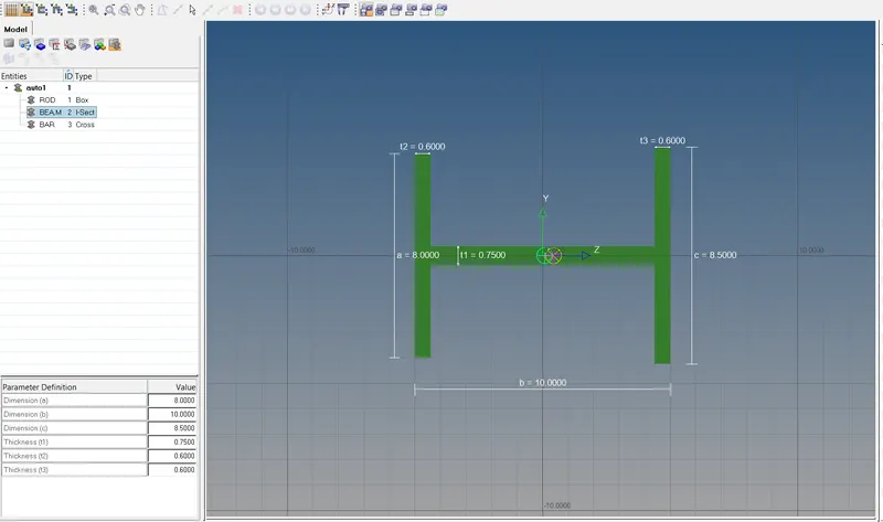
Cross-Section: I Section- Dimension a= 8 mm

Dimension b= 10 mm

Dimension c= 8.5 mm

Thickness t1= 0.75 mm

Thickness t2= .6 mm

Thickness t3= .6 mm

c. Bar element:- Constrain only x and y DOFs With RBE3 link

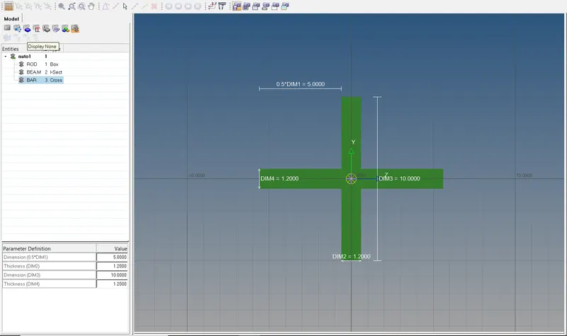
Cross-section: X section- Dimension DIM1= 5 mm

Thickness DIM2= 1.2 mm

Dimension DIM3= 10 mm

Thickness DIM4= 1.2mm

d. & e. Apply the mass of magnitude 10 with the RBE2 link

f. Join the two components with Spring elements

PROCEDURE:-

1.To import the model into the workspace

FILE>IMPORT>GEOMETRY>after selecting the desired geometry we click on the import button.

our geometry will be visible in the workspace.the reason is to select the geometry option is because our file is in .IGS format.after importing the PARALLEL_BRACKET.IGS our workspace will look like this.
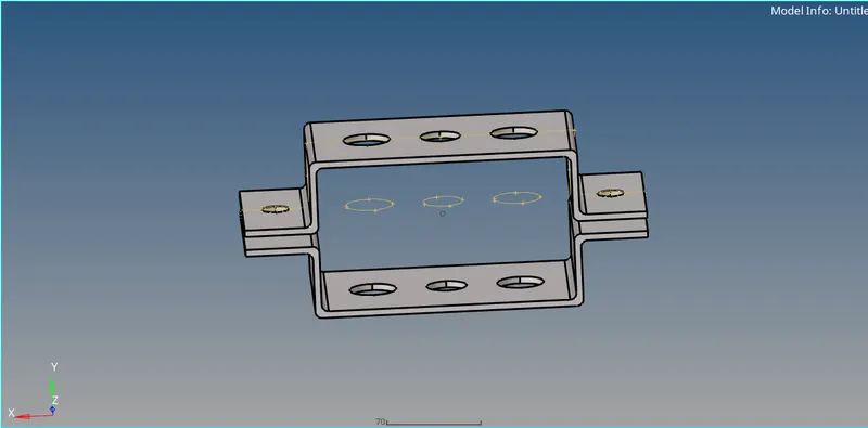
this is our desire geometry on which we are going to create a 1D element.

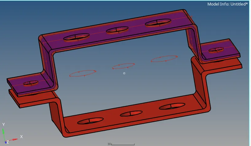
2) To create a 1D element first we need to do mid-surfacing of both the upper and lower bracket.
What is mid-surfacing?
Midsurface modeling is a technique for creating a simplified shell representation of a solid model. Midsurface modeling can reduce the computational expense of analyzing a complete solid model when a shell model with a defined thickness and fewer details is suitable for the required analysis.
-here we are using auto mid surfacing as our component having even thickness automatically so we can extract our mid surfaces.
for the upper bracket,
GEOMETRY>MIDSURFACE>AUTOMIDSURFACE>AUTOEXTRACTION> we selected the upper surface which we are going for mid-surface and the>EXTRACT
and geometry will look like this.
after extracting mid surface for the upper bracket there will be mid surface entity will be created in a tree and we are going to rename it as bracket_1 and adding one more component as bracket_2
same procedure we going to follow for a lower bracket,
-after extracting the mid surface for lower bracket there will be one more mid surface will be created in the model tree section
3.Deleting the solid part
-To delete the solid part we will click on then changing the option into solid then selecting the solid and deleting the entity.
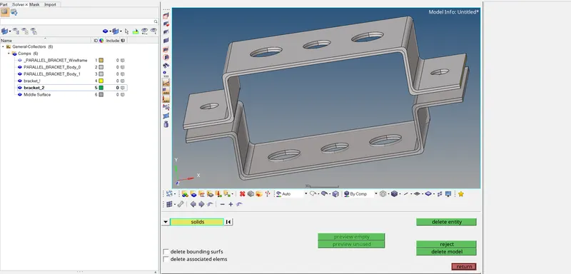
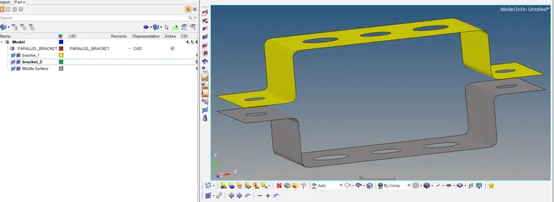
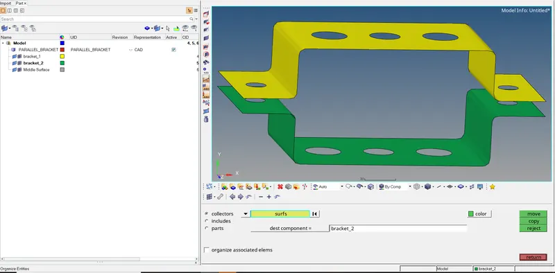
-now we will move the mid surface of the second bracket in bracket_2 by this method
-after that, we will delete the all other previous components and our model will look like this with only mid surfaces.
TOOL>ORGANIZE>, COLLECTORS,>the selecting the destination and >MOVE
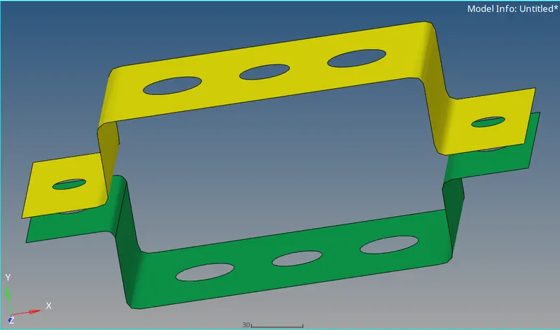
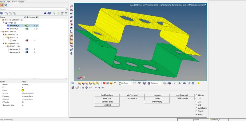
then we will be deleting the solid parts and keeping the only mid surface entities in a tree which are bracket_1 and bracket_2 and assign them different colors yellow and green respectively.
and our final mid surface will look like this,
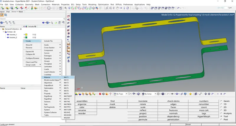
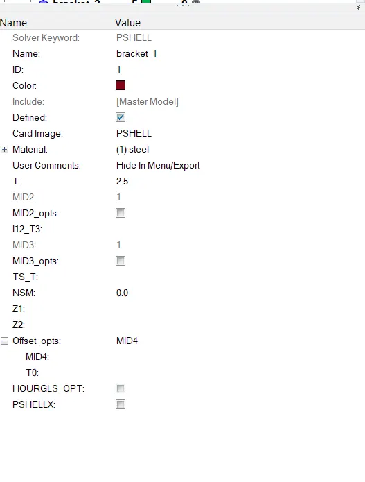
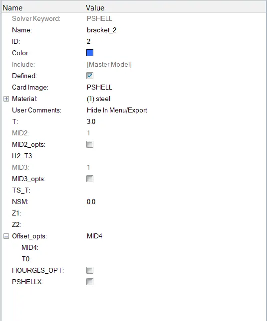
and creating the properties for both the brackets by clicking on create section and
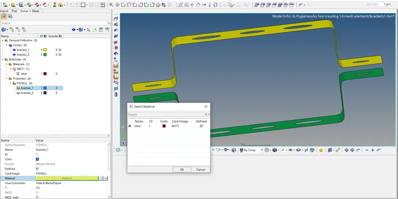
and selecting the thickness for both brackets as bracket_1 t=2.5 and bracket_2 t=3 and property as PSHELL because we are using plain surfaces
properties for both the bracket,
for bracket_!
for bracket_2
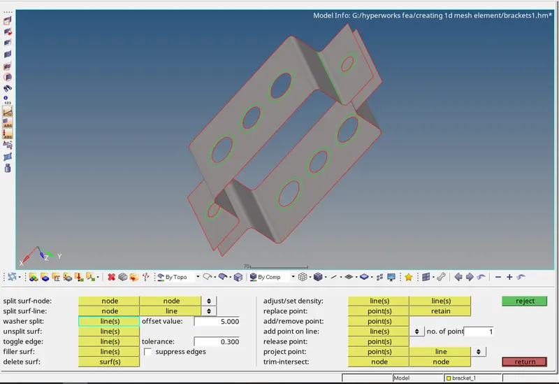
4.now creating washer split at around each hole for good mesh.
GEOMETRY>QUICK EDIT>WASHER SPLIT>selecting the offset values to 5 units and clicking on the holes where we want to create a washer split.
5.creating 2D mesh at both the surfaces
2D>AUTOMESH>SURFACE(selecting the surfaces)>ELEMENT SIZE to 5 and>ELEMENT TYPE TO quads>MESH
6.Creating 1D element at given locations
first, we need to create sections for element
so we will go to,
1D>HYPERBEAM>STANDARD SECTION>STANDARD SECTION LIBRARY>STANDARD SECTION TYPE
this how we created the three-section with given dimensions.
ROD ELEMENT:(BOX)
BEAM ELEMENT:-(I-SECTION)
BAR ELEMENT:-(X-SECTION)
after creating this we will move to our model window
-there will be an entity of name auto1 below beam section and collector in the model tree section which will be using when we are giving cross-section to components
-so first we are going to place,
RBE2 AND RBE3

RBAR and RBE2 Elements:

The RBAR or RBE2 element can be used for connecting two nodes to model a ‘rigid’ welded type connection, with all 6 DOFs, or a pinned connection with 3 translational DOFs.

The RBE2 element can also be used to model a wagon wheel type connection between the independent and the dependent nodes. RBAR and RBE2 elements artificially add stiffness by constraining the system to follow a one-to-one linear displacement and/or rotational relationship between the connected nodes.

RBE3 Elements:

Comparing RBE2 Vs RBE3 elements, RBE3 on the other hand is not a ‘rigid’ element so to speak. The motion at the ‘dependent’ node is a weighted average of the motion at the ‘independent’ nodes. This is why it is also known as an ‘interpolation’ R element. RBE3 elements do not add artificial stiffness to the structure like the RBAR or RBE2 elements do.

By default, the reference node (the single node at the tip of the element) DOF will be the ‘dependent’ DOF. Also, note that the dependent DOF cannot be constrained (or omitted or supported, which I never tried to do or use personally). They are also not allowed to be part of another RBE element or MPC equation.
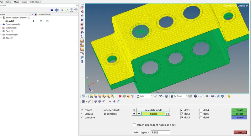
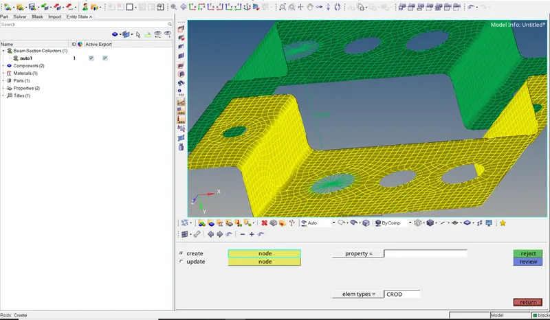
A)ROD ELEMENT
at the hole, we are going to have ROD element,
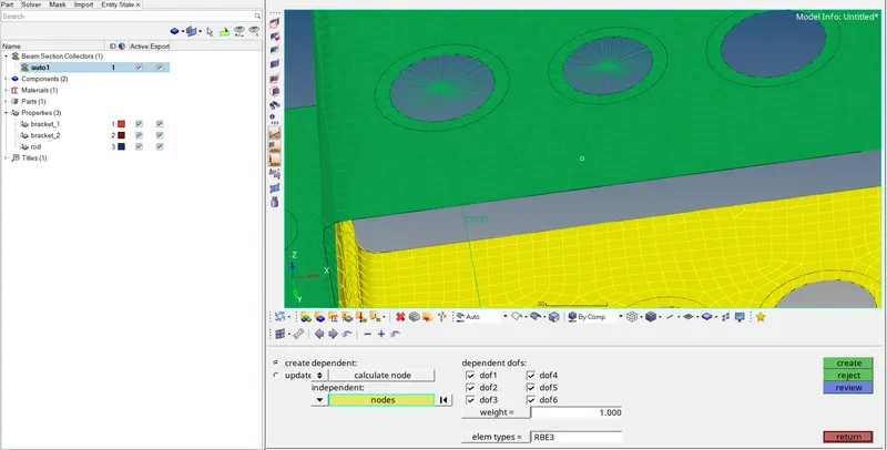
for that, we are going to create an RBE2 link to connect the element at both the location 'a' of the upper bracket and lower bracket
To create an RBE2 link
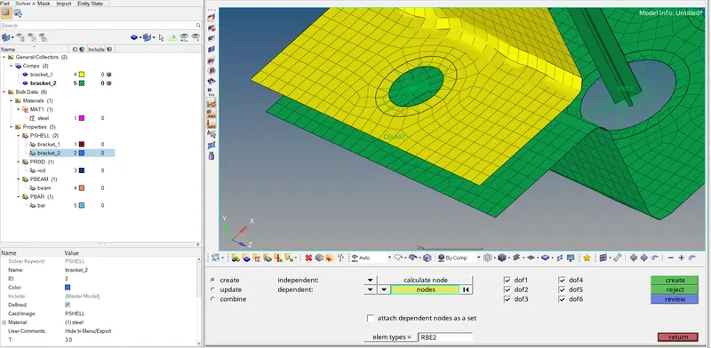
1D>RIGIDS>CREATE>CALCULATE NODES>MULTIPLE NODES>then selecting the nodes in the region of hole and washer split of location a>and giving DOF as a given condition to constrained only translational motion >CREATE
A similar procedure we are going to conduct for the lower bracket at location 'a'
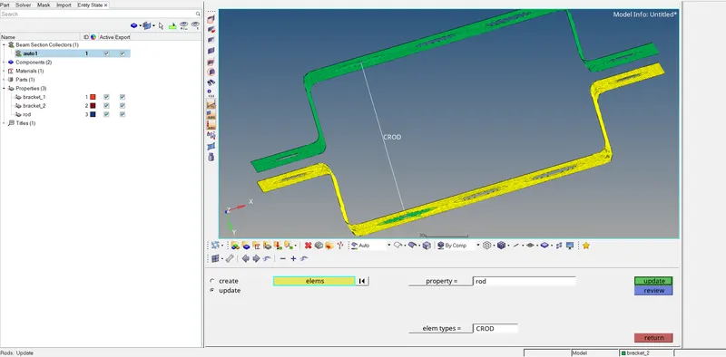
after creating at both the side we are going to create ROD element,
1D>RODS>CREATE>NODES(selecting the nodes of the junction point of both the RBE2 links of both brackets>TAB
and rod element will be created
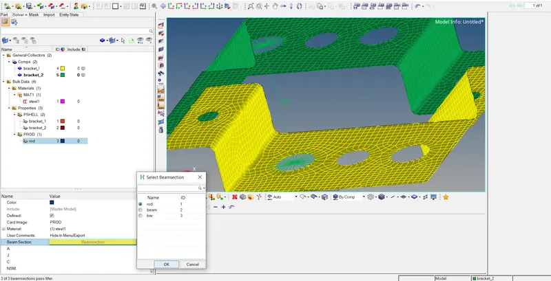
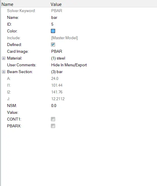
creating properties for rod and choosing cross-section,
by clicking
RIGHT CLICK in entity state (of mouse)>create >property>PROD(because our element is ROD.
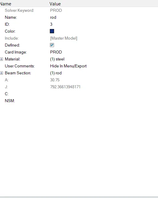
now updating properties for ROD element,
B)BEAM ELEMENT
-creating RBE3 link on both the brackets at the hole location 'be with all DOF are constrained.
now creating BEAM element,
-selecting nodes of both the RBE3 link junction point and selecting the cross-section and hitting TAB and beam will be created
now creating the property in the model entity,
RIGHT CLICK in entity state (of the mouse)>create >property>PBEAM(because our element is BEAM)
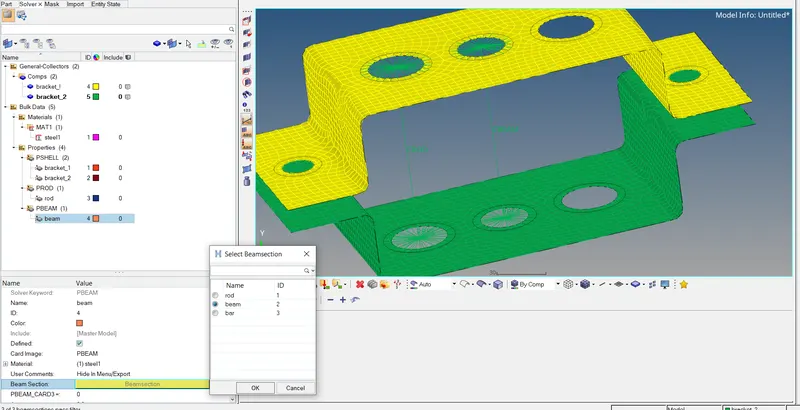
now selecting the cross-section and property,
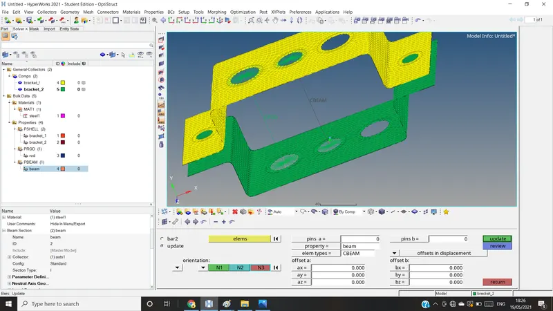
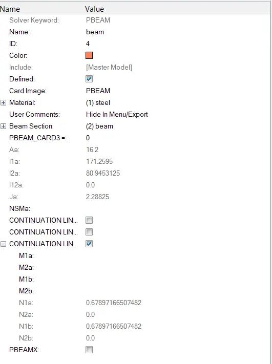
now updating the properties of beam element,
1D>BARS>UPDATE>ELEMENT(selecting element)>CROSSECTION>PROPERTY(choose as BEAM)>ELEMENT TYPE)choose as CBEAM>and UPDATE
C)BAR ELEMENT:
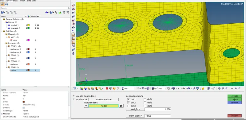
-creating an RBE3 link on a hole at location 'c' with DOF constraining x and y-direction will be constrained.
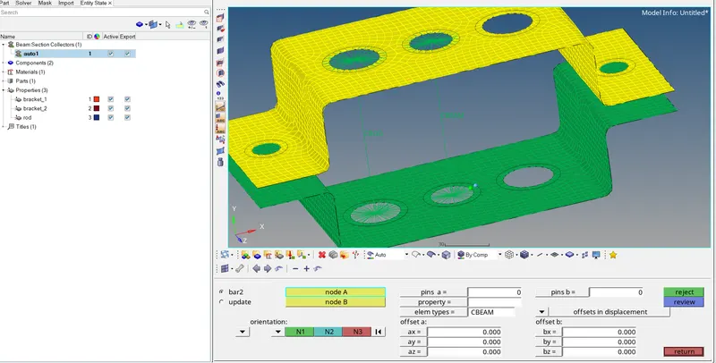
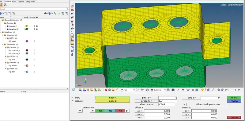
-now we will create a bar at location 'c' by joining the junction point of the RBE3 element,
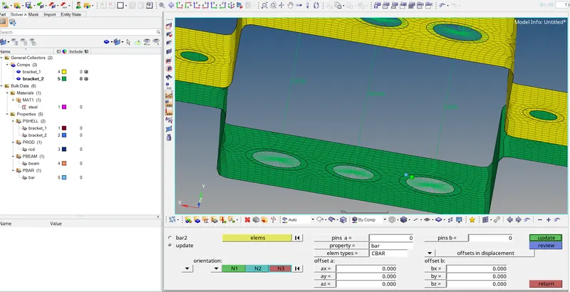
1D>BAR2>NODE(joining both the junction node of RBE3 link)>CROSSECTION>PROPERT(bar)>ELEMENT TYPE(CBAR)>TAB
and bar will be created ,
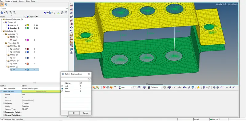
now updating crosssection for bar,
selecting bar as beam section.
-now updating properties for bar,
by clicking,
1D>BARS>UPDATE>ELEMENT(selecting element)>CROSSECTION>PROPERTY(bar)>ELEMENT TYPE (CBAR)>UPDATE
properties for,
ROD ELEMENT,
BEAM ELEMENT,
BAR ELEMENT,
D) MASS ELEMENT
now creating a mass of magnitude 10 units at all the corner hole of both the brackets at location 'd' and 'e'
-first creating RBE2 element at the hole,
1D>RIGIDS>CREATE>CALCULATE NODE>MULTIPLES NODE>DOF(all constrained)>CREATE
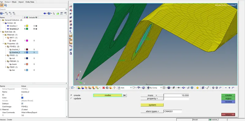
-now applying the masses to the junction point of the RBE2 link

-1D>MASSES>CREATE>NODE(selecting the junction point of RBE2 element>MASS(10 unit)>ELEMENT TYPE(CMASS1)>CREATE

and mass will be created

(Note:-same procedure we are going to follow for all both the corner holes at location 'd' and 'e' of both the brackets.)

E)SPRING ELEMENT

-joining the brackets with spring element at location 'f'
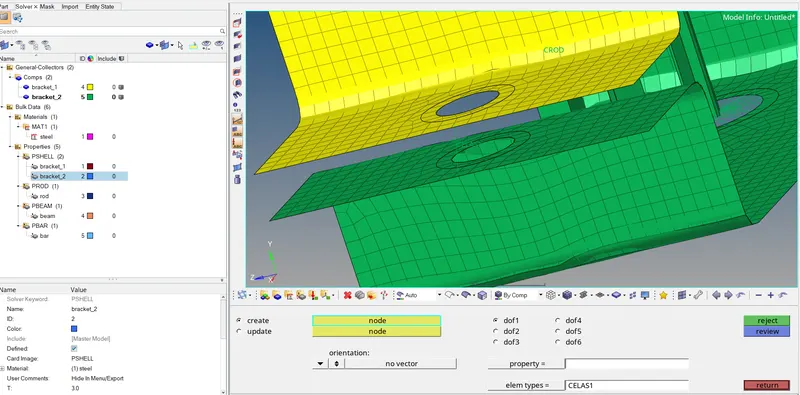
-to create spring element,

1D>SPRINGS>CREATE>NODE(selecting the node of both the end surface of bracket)>DOF(only x is constrained by default)>ELEMENT TYPE(CELAS1)>TAB

and spring will be created

(Note:same procedure we need to follow for either side of bracket)

RESULTS:-

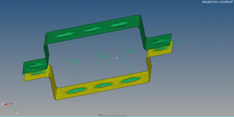
1)after creating the elements
2)after applying the 1d detailed element representation
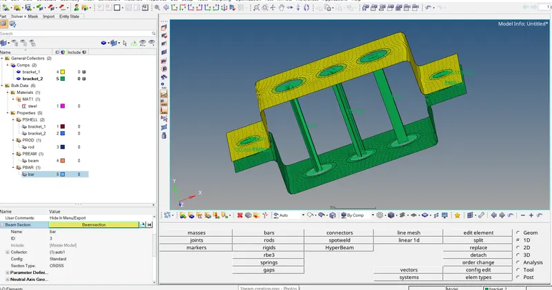
3)closer view of bracket to check cross section of created elements,
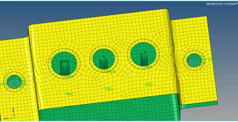
4) mass and spring element at right side,
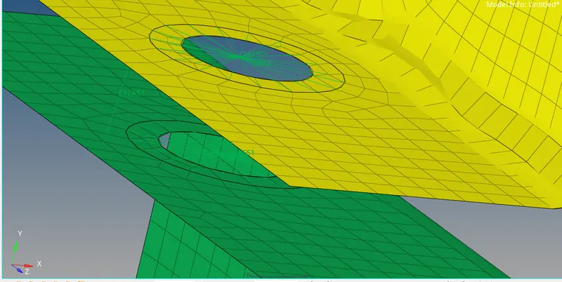
5)mass and spring element at left side
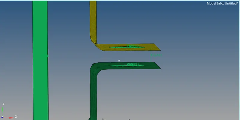
CONCLUSION:-

1D element will provide a much organize result but less detail which require less effort in the interpretation of results. 2D and 3D FEA results are displayed in the form of tensor, which provide more details for each section of the structure but also require more effort to interpret the results.

Your portfolio, next

Ship work like this
in your own course.

Talk to a career counsellor

Free 20-minute call. We'll map the right course to where you want to work.

By submitting you agree to our Terms and Privacy Policy.

Talk to a career counsellor

Free 20-minute call. We'll map the right course to where you want to work.

By submitting you agree to our Terms and Privacy Policy.