Week 4-1D Element Creation Challenge
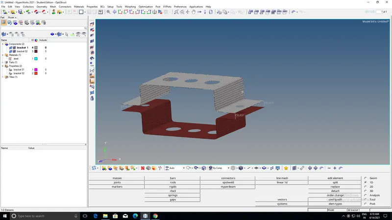
Mesh the Given component with the Size of 5 Units. Create 1D elements on the following component with given cross-section and DOF
a. Rod element:- Translational DOF should be Constrained with RBE2 link
Cross-Section: BOX- Dimension a= 12 mm
dimension b=10 mm
Thickness t= 0.75 mm
step 1: Firstly import the given geometry by the following options import ,geometry because the file is in IGES. format.
step 2:Apply the mid surface for both the brackets naming bracket 01 and bracket 02.
step 3:Delete the wireframe model and the other solid components and to represent the mid surface into CAD model we have to to create material called steel and giving thickness in properties then go to 2D geometry click on auto mesh and increase or decrease the nodes to get a proper mesh.
step 4: Then create the RBE2 elements at required nodes as per given question then select the element type called rod element and constraint the tanstition DOF and then select the cross section x then give the dimension in hyperbeam page as per alloted.
step 5: Then create a property in tab bar import all the dimensions into their respective element and update in 1D in rod element .
step 6:Finally click on 1D detailed element representation.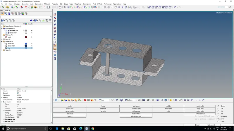
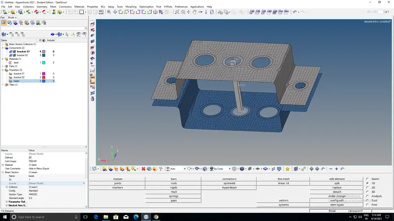
b. Beam element:- All DOF should be constrained with RBE3 link
Cross-Section: I Section- Dimension a= 8 mm
Dimension b= 10 mm
Dimension c= 8.5 mm
Thickness t1= 0.75 mm
Thickness t2= .6 mm
Thickness t3= .6 mm
step 1: Firstly import the given geometry by the following options import ,geometry because the file is in IGES. format.
step 2:Apply the mid surface for both the brackets naming bracket 01 and bracket 02.
step 3:Delete the wireframe model and the other solid components and to represent the mid surface into CAD model we have to to create material called steel and giving thickness in properties then go to 2D geometry click on auto mesh and increase or decrease the nodes to get a proper mesh.
step 4: Then create the RBE3 elements at required nodes as per given question then select the element type called rod element and constraint the ALL DOF and then select the cross section I then give the dimension in hyperbeam page as per alloted.
step 5: Then create a property in tab bar import all the dimensions into their respective element and update in 1D in BEAM element .
step 6:Finally click on 1D detailed element representation.
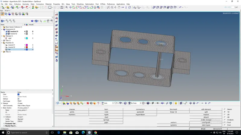
c. Bar element:- Constrain only x and y DOFs With RBE3 link
Cross-section: X section- Dimension DIM1= 5 mm
Thickness DIM2= 1.2 mm
Dimension DIM3= 10 mm
Thickness DIM4= 1.2mm
step 1: Firstly import the given geometry by the following options import ,geometry because the file is in IGES. format.
step 2:Apply the mid surface for both the brackets naming bracket 01 and bracket 02.
step 3:Delete the wireframe model and the other solid components and to represent the mid surface into CAD model we have to to create material called steel and giving thickness in properties then go to 2D geometry click on auto mesh and increase or decrease the nodes to get a proper mesh.
step 4: Then create the RBE3 elements at required nodes as per given question then select the element type called rod element and constraint the TRANSITION X AND Y DOF and then select the cross section I then give the dimension in hyperbeam page as per alloted.
step 5: Then create a property in tab bar import all the dimensions into their respective element and update in 1D in BAR element .
step 6:Finally click on 1D detailed element representation
d. & e. Apply the mass of magnitude 10 with the RBE2 link
step 1: Firstly import the given geometry by the following options import ,geometry because the file is in IGES. format.
step 2:Apply the mid surface for both the brackets naming bracket 01 and bracket 02.
step 3:Delete the wireframe model and the other solid components and to represent the mid surface into CAD model we have to to create material called steel and giving thickness in properties then go to 2D geometry click on auto mesh and increase or decrease the nodes to get a proper mesh.
step 4: Then click on the mass and give nodes by giving magnitude 10 and then create.
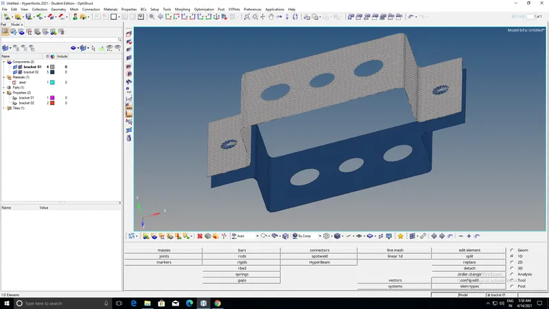
f. Join the two components with Spring elements
step 1: Firstly import the given geometry by the following options import ,geometry because the file is in IGES. format.
step 2:Apply the mid surface for both the brackets naming bracket 01 and bracket 02.
step 3:Delete the wireframe model and the other solid components and to represent the mid surface into CAD model we have to to create material called steel and giving thickness in properties then go to 2D geometry click on auto mesh and increase or decrease the nodes to get a proper mesh.
step 4:And click on 1D geometry and goto springs allot nodes at the respective ends of the given component thus the springs has been alloted to the particular component.