Week 12:Project-1-Meshing of Door Inner Panel Challenge
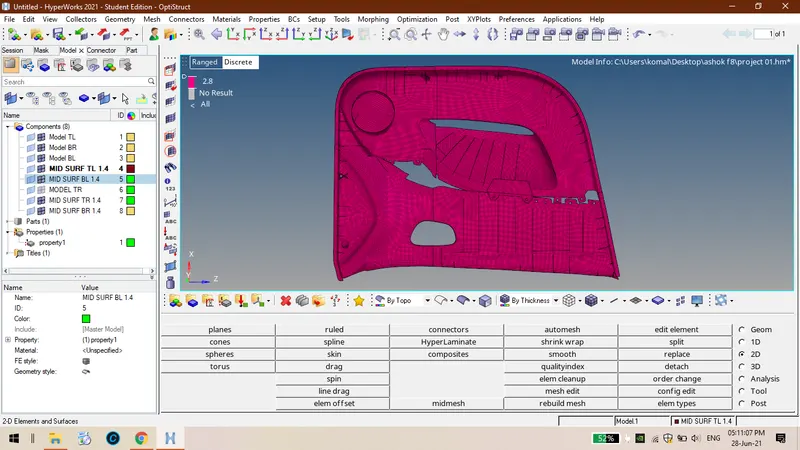
AIM: To extract the mid surface and generate mesh on the mid surface and alloting thickness to the midsurface. using the given criteria.
PROCEDURE:
OPENING THE FILE:
STEP 01:The given file is in .iges file , follow the below steps to import the model.
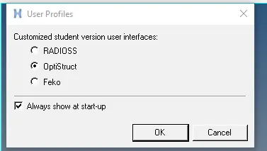
STEP 02:IN main bar select import >>select geometry>>select file>>import.
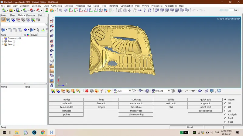
STEP 03: The file will be opened in the graphics window to view the component press 'f'.
EXTRACTING THE MID SURFACE:
STEP 01: Hence given component is varying in thickness and also it is a plastic component so auto mid surface is applicable.
STEP 02:So manual mid surface is the only process to extract mid surface to the given component , by following below steps mid surface can be extracted.
STEP 03: In geometry tab select surface edit>>select offset option>>select surface for mid surface>>click on surafces>>select duplicates >>select current component>>give offset value>> check the vector normal direction>> if direction is in opposite reverse the normal.


STEP 04: Firstly have to defeature the surface fillets of these ribs by giving surface fillet radius range must be 0.1 to 15.
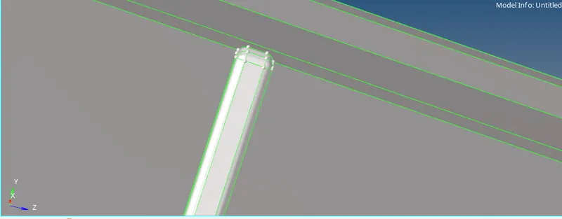
STEP 05: In geometry tab>>select defeature>>surface fillets>>give radius range is 0.1 as min radius and 15 as max radius>> select the surfaces then defeature.

STEP 06 : Then the mid suface cant be extracted directly to these ribs , firstly create mid line by using surfaces then trim the surface and then extende the line to the surface by following steps.
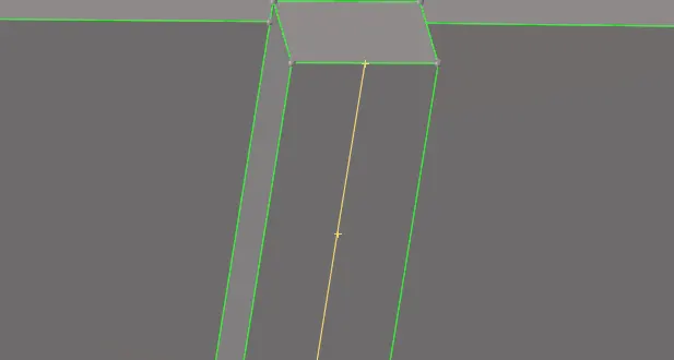
STEP 07: To create midsurface for the ribs follow the steps goto geometry tab>> lines>>mid line>>select line list >>create >> mid line will be created between the surfaces>>go to surface edit>>select trim with lines>>select surface>>select free lines {keep in normal to surface mode}>>trim.


STEP 08:In geometry rab >>surface edit>>extend>>keep in extend over edges option>>select lines for lines to extend>>select surfaces to target>> extend.

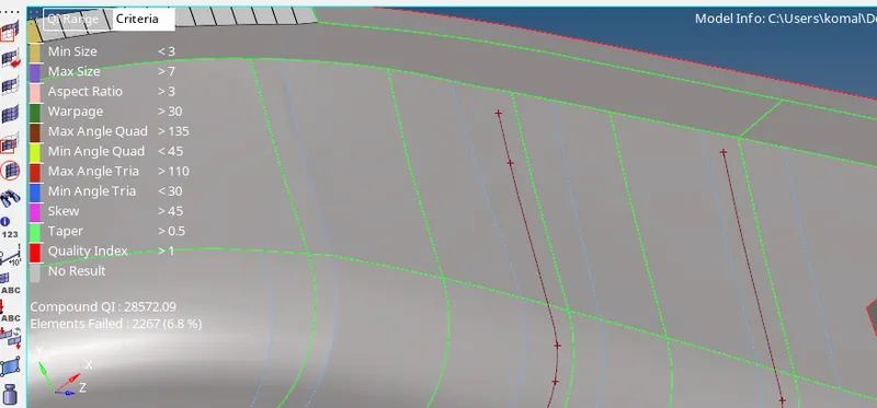
STEP 09: In geometry tab >> select surafces >> select ruled option>> select the lines>>create . Then the surafce will be created between the lines.


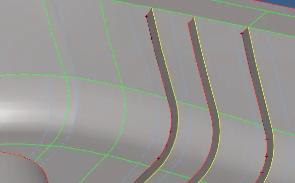
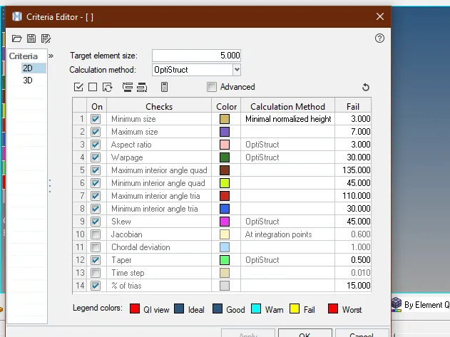
STEP 10:After that the whole mid surface will be extracted including ribs etc.. then input the quality criteria and start meshing on the mid surface.
GENERATING THE MESH ON COMPONENT:
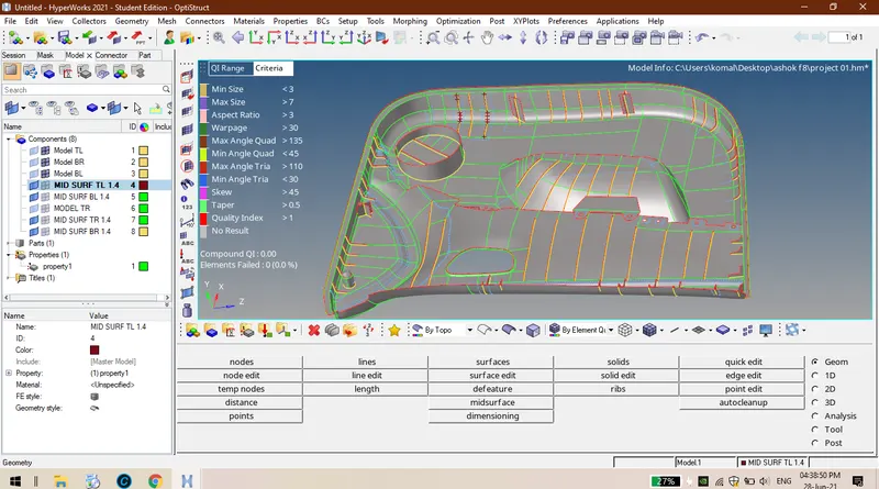
STEP 11:to craete mesh on the mid surface go to 2D tab >>automesh>>select surface>> enter taget element size>> mesh.


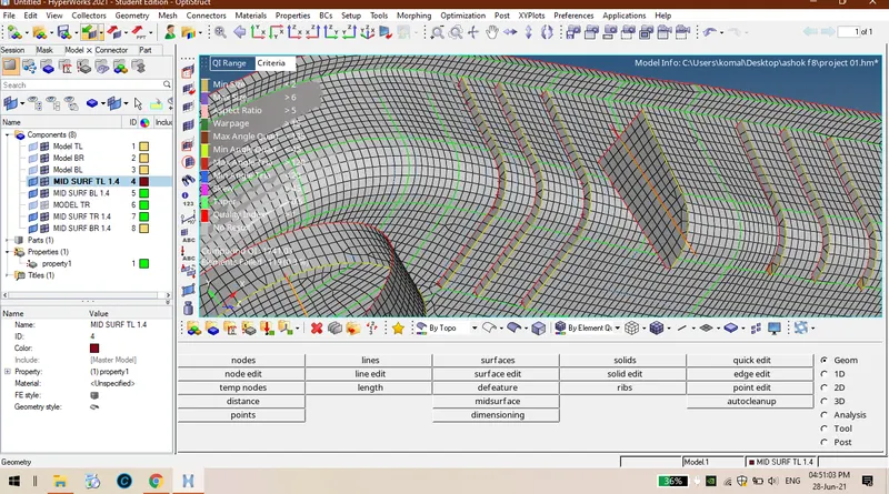
STEP 12:If the mesh flow is not proper select that particular region elements then again remesh it so that the mesh flow and element failure will be rectified and flow is also good.
STEP 13:If there is any element failures then we have to rectify them using available tools like element optimization and drag tria options.
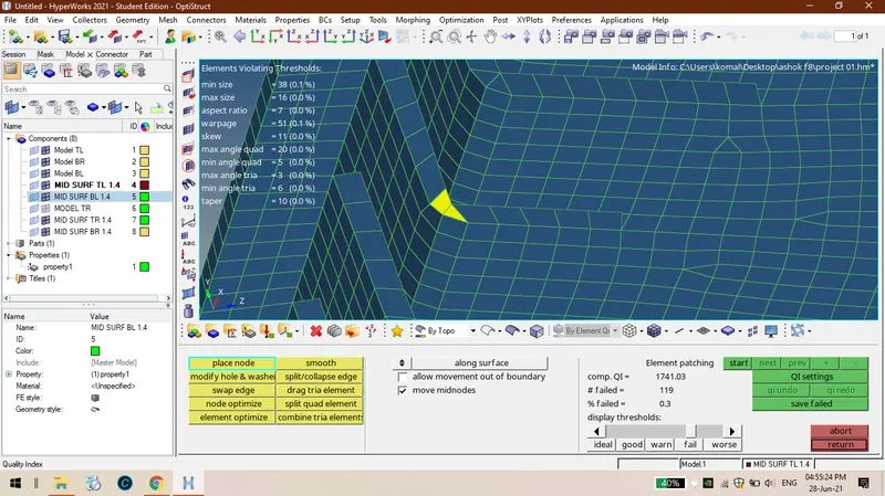
STEP 14:For rectification of elemental failures go to 2D geometry>>quality index.

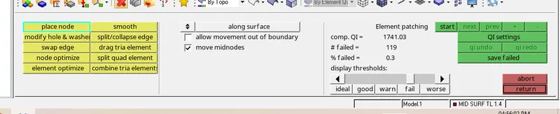
PLACE NODE: Moving the node from one position to anoter position it is notinh but a changing the postion of node.
SWAP EDGE: There is a thumb rule that no trias must be there at edges for that the swap edge is used , the trais at free edge can be eliminated.
ELEMENT OPTIMISATION: It is nothing rearranging the surrounding elemnts of the failure element so that the element can be reactified from te failures.
DRAG TRIAS: Tis option is used to remove trais on te component and also play a key role in minimisin the number of trais.
COMBINE TRIA ELEMENTS: This is used to combine the two trais elements and to combine them in to a quad element.
SMOOTH: Its is very important parameter what ever may be the option we used form the above options after that smoothing must be done to get proper mesh flow so that the mesh of the component will be good.
ASSINGING THICKNEES TO MIDSURFACE:
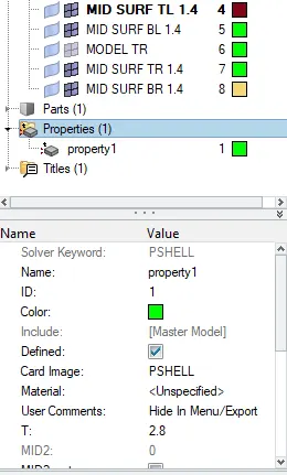
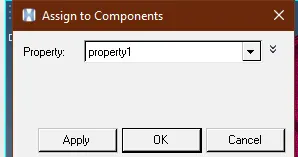
>>In parent tree rit click>>create>>property>>allot tickness value T=2.8, so assin tickness to te component.
CONCLUSION:
Finally EXTRACTION OF MID SURFACE AND MESIN ON MID SURFACE AND ASSININ TICKNESS TO TE COMPONENT AS BEEN DONE.
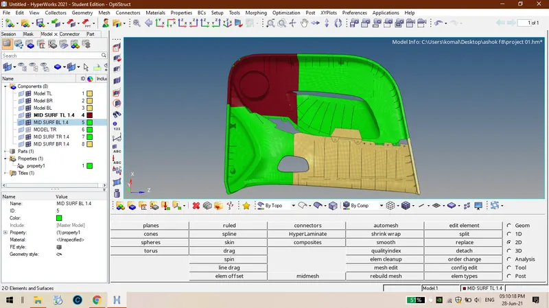
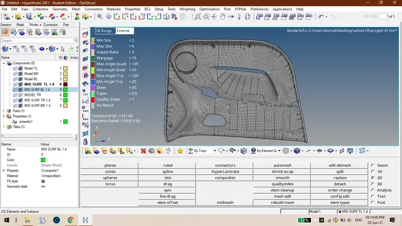
After assingin tickness to component