1D Element Creation using Hypermesh
Aim :
To create 1D elements on the given component with given cross-section and DOF using Hypermesh.
Specification :
- Rod element(a):- Translational DOF should be Constrained with RBE2 link
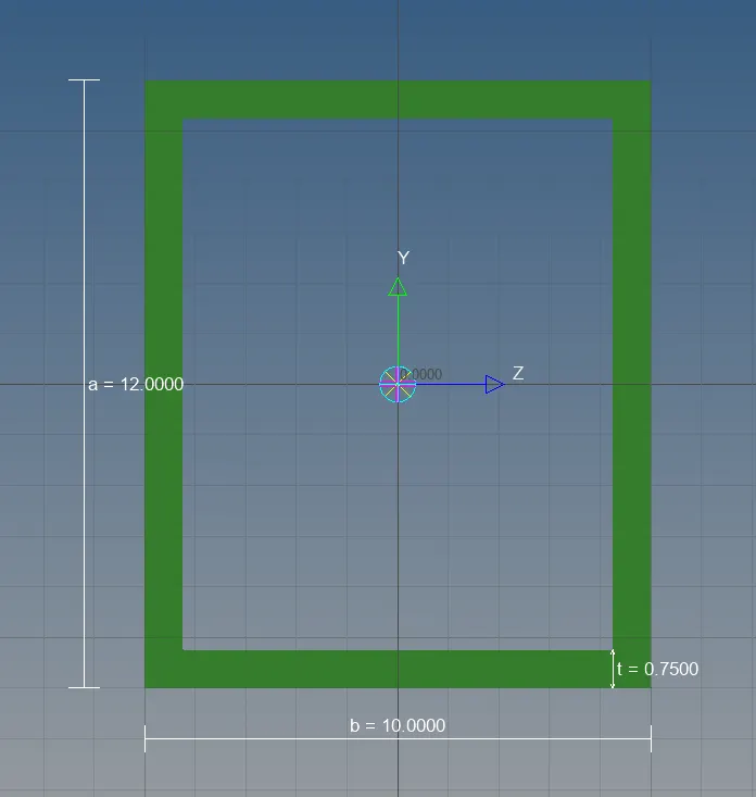
Cross-Section: BOX
Dimension :
a= 12 mm
b=10 mm
t= 0.75 mm - Beam element(b):- All DOF should be constrained with RBE3 link
Cross-Section: I Section
Dimension :
a= 8 mm
b= 10 mm
c= 8.5 mm
t1= 0.75 mm
t2= .6 mm
t3= .6 mm - Bar element(c):- Constrain only x and y DOFs With RBE3 link
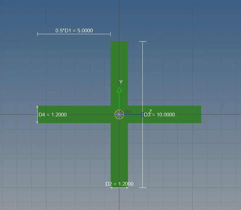
Cross-section: X section
Dimension
DIM1= 5 mm
DIM2= 1.2 mm
DIM3= 10 mm
DIM4= 1.2mm - (d) & (e) Apply the mass of magnitude 10 with the RBE2 link
- (f) Join the two components with Spring elements
Procedure :
Geometric Cleanup and Meshing
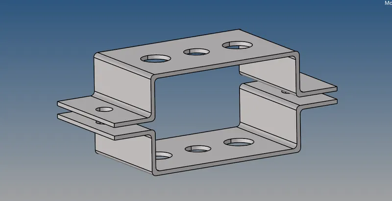
- Import the geometry into the workspace and change the wireframe to solid. Using the Autocleanup tool perform a cleanup operation and also remove the unnecessary lines.
- After Cleanup, extract the Midsurface . Geom>Midsurface>Select all the surfaces>Extract.
Make sure the extraction is set to "Auto Extraction" and "Offset-Planes" is selected so that we can get all the edges. Assign each Midsurface formed to new components "Bracket_1" and "Bracket_2".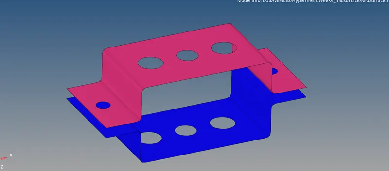
- Before meshing, we need to create washer splits near the hole region for a smooth mesh. Washer split offset with 4mm. Generate the mesh with element size of 5mm with Quad element type. After meshing delete or supress the Solid model thus we obtain the below:
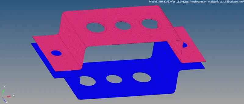
Creation of 1D Elements :
- We have to create Rigid Links :
RBE2 Link : 1D>Rigids>Select Nodes>Create . Created at locations "a", "d" and "e" for Bracket_1 and Breacket_2. Keel all the DOF constrained in X, Y and Z Translation direction. - RBE3 Link : 1D>RBE3>Select Nodes>Create . Create at "b" and "c" keeping DOF constraind only in X and Y for the link at "c" and all DOF at link "b".
- For links at "d" and "e" apply mass to the Master node of RBE2 links. 1D>Masses>Select master Node for mass of 10 units. For spring connection at location "f", 1D>Spotweld>Using nodes>Element = CELAS1>Select the nodes.
- In order to create the section of Rod, Beam and Bar elements, In Hyper Beam tool, select the respective Cross-Section for creating 1D element and give the assigned dimention to the given geometry.
- Rod Element :
- Beam Element :

- Bar Element :
- Rod Element :
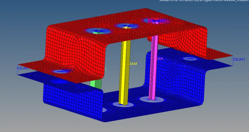
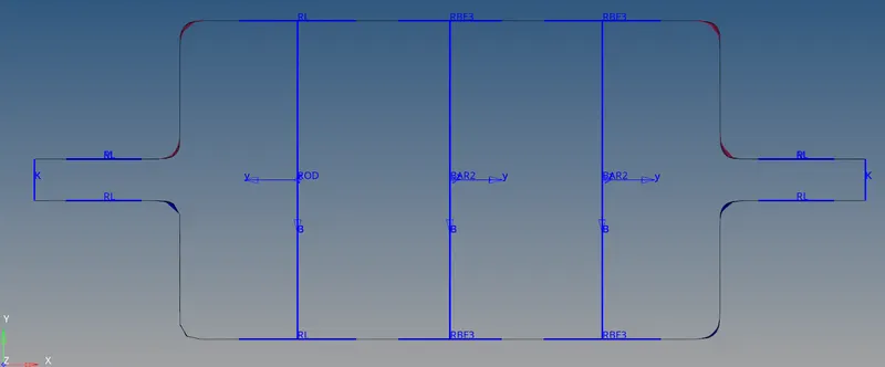
- After selecting the exact cross-section for the connections and updating each of the components. The connections are created with different elements.
Result :
After doing all the necessary connections and meshing we obtain :
Conclusion :
- Extracted the mid-surface for the given component and created a Mesh.
- Deployed various connections using 1D Element.
- Created Solid representaions of 1D elements.
- Hypermesh is very useful for accurate Preprocessing.