Week 4-1D Element Creation Challenge
1D Element Creation
OBJECTIVE:
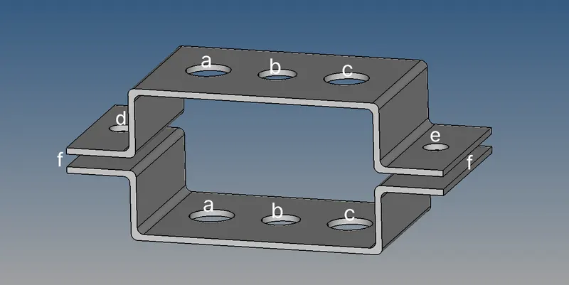
1.Mesh the Given component with the Size of 5 Units. Create 1D elements on the given component with given cross-section and DOF
2.(a) Rod element:- Translational DOF should be Constrained with RBE2 link
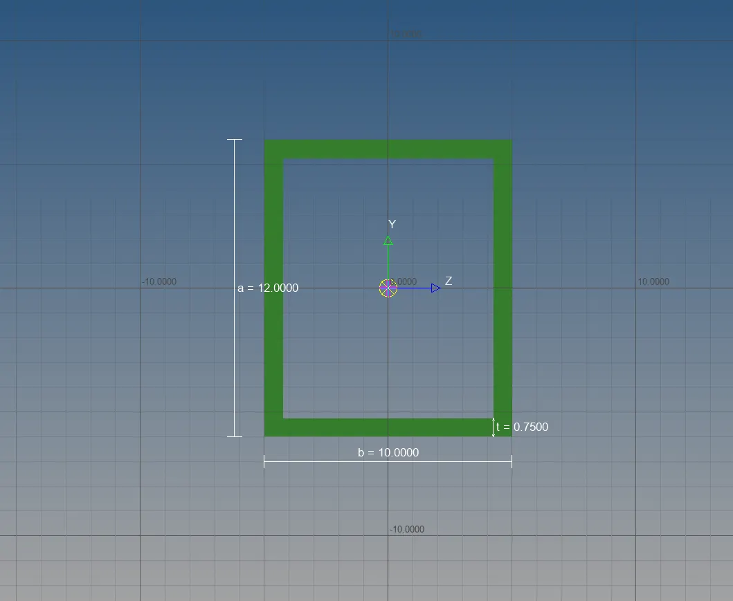
Cross-Section: BOX- Dimension a= 12 mm
dimension b=10 mm
Thickness t= 0.75 mm
3.(b) Beam element:- All DOF should be constrained with RBE3 link
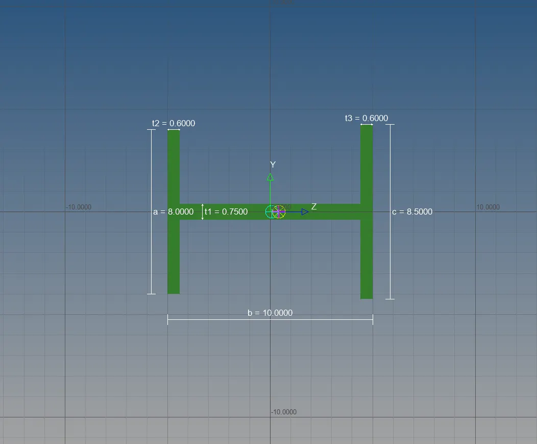
Cross-Section: I Section- Dimension a= 8 mm
Dimension b= 10 mm
Dimension c= 8.5 mm
Thickness t1= 0.75 mm
Thickness t2= .6 mm
Thickness t3= .6 mm
4.(c) Bar element:- Constrain only x and y DOFs With RBE3 link
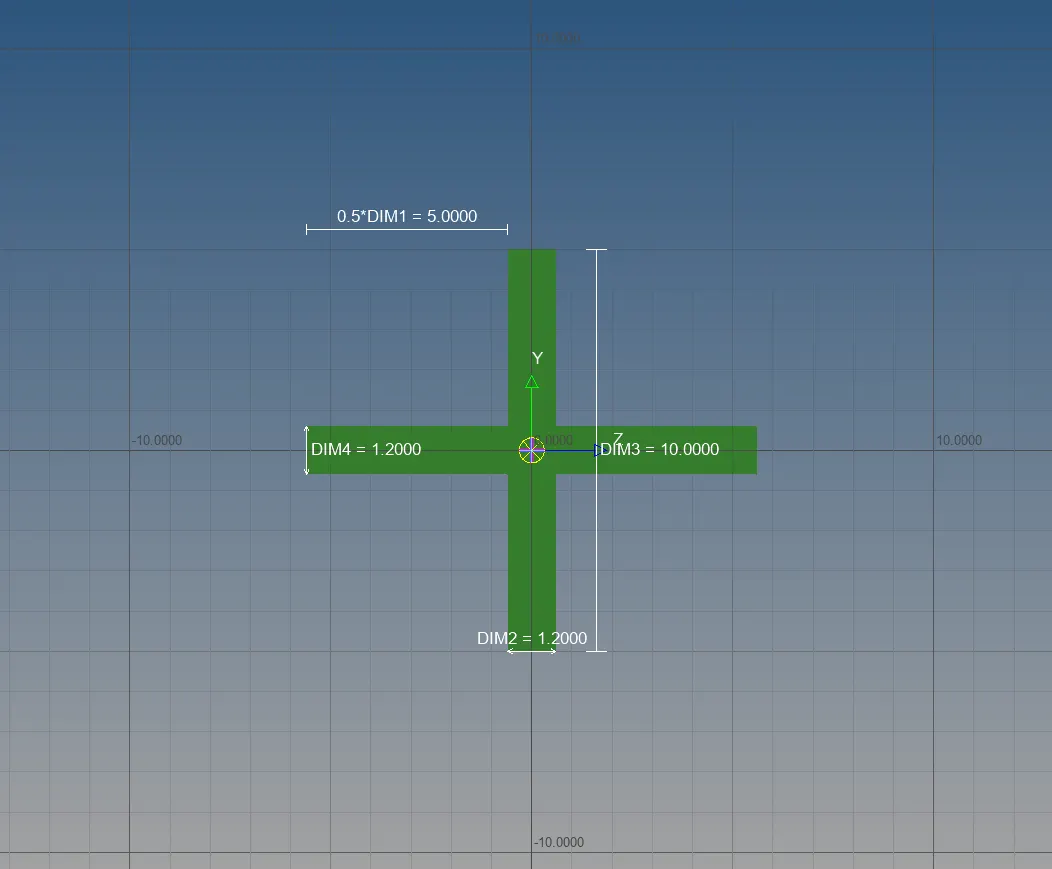
Cross-section: X section- Dimension DIM1= 5 mm
Thickness DIM2= 1.2 mm
Dimension DIM3= 10 mm
Thickness DIM4= 1.2mm
5.(d) & (e) Apply the mass of magnitude 10 with the RBE2 link
6.(f) Join the two components with Spring elements
PROCEDURE :
- IMPORT MODEL
- Go to FILE >> IMPORT >> MODEL >> SELECT(MODEL) >> IMPORT
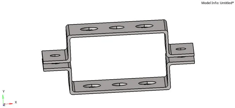
The file is IGS format
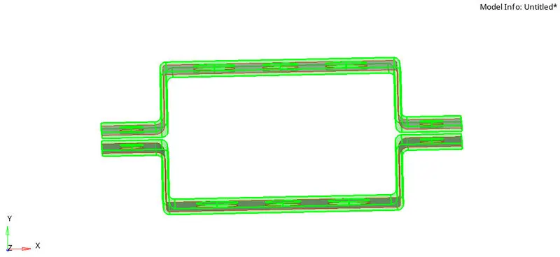
- MID SURFACEING
- To convert the given 3D model to 2D use mid surface
- Mid surface we can do in different manner we have to select the proper option (skin offset) , I have try all option but only skin offset provide proper edge of the model
- GEOMETRY >> MID SURFACE >> SELECT ELEMENT >> AUTO MID SURFACE
- ORGNIZE THE COMPONENT
- After we create the mid surface we have to organize the mid surface to proper address ,I give it as bracket _1, bracket_2
- TOOL >> ORGNIZE >> SELECT (ELEMENT) >> MOVE
- CREATE MATERIAL AND PROPERTY OF BRACKET
- RIGHT CLICK ON MOUCE >> CREATE>> MATERIAL >> SELECT (PROPER DATA)
- RIGHT CLICK ON MOUCE >> CREATE >> PROPERTY >> SELECT (PROPER MATERIAL , ELEMENT TYPE AND THICKNESS)
- Rename based on our requirement in material (steel) and property (bracket1,bracket2)
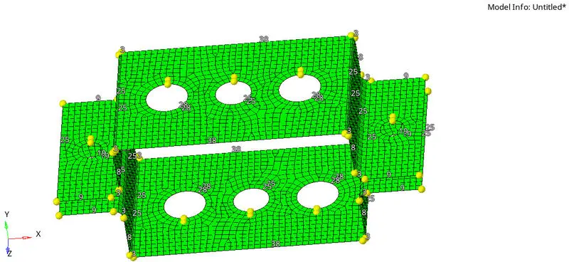
- MESH THE SURFACE
- Before mesh the surface create washer split from quick edit with offset of 5mm
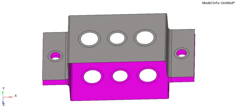
- 2D >>AUTO MESH >> SELECT ELEMENT >>MESH
- Element size as 5mm and mixed type
- Rearrange the mesh in fillet and in hole to get proper mesh in edges by increasing number of nodes
- CONNECTERS AS PER QUISTION
- a,d,e are RBE2 element
- 1D >> RIGIDE >> SELECT NODE
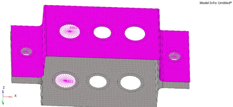
- b,c are RBE3 element
- 1D >> RBE3 >> SELECT NODE
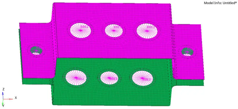
- f Join the two components with Spring elements
- CREATE HYPER BEAM
- 1D >> STANDARD SECTION >> HYPER BEAM >> SELECT(TYPE) >> APPLY PARAMETER >> CREATE
- CREATE ELEMENT
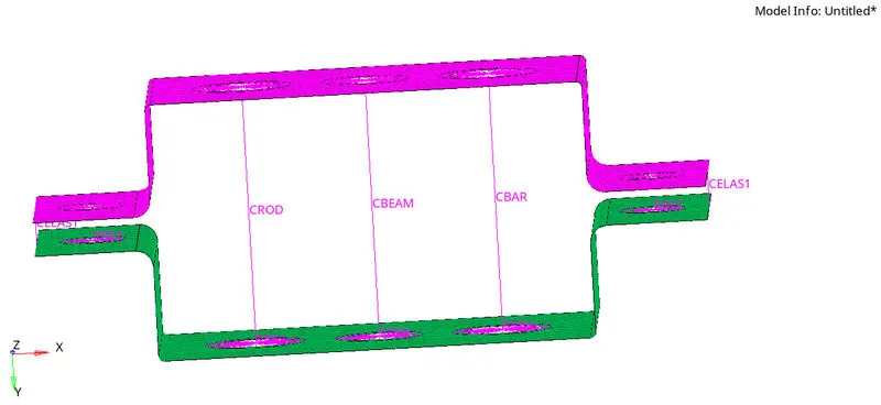
- Create rod , beam and bar as per question
- 1D >> (ROD\BEAM\BAR) >> SELECT NODE AND VECTOR >>CREATE
- Also apply DOF in each element as per quistion
- CREATE ELEMENTS IN PROPERTY AND UPDATE
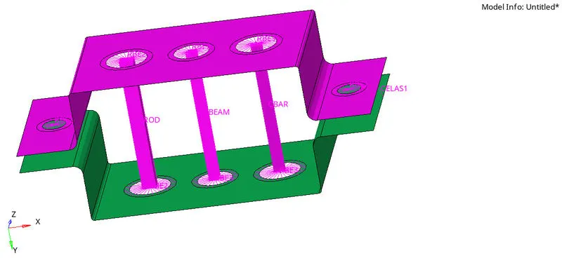
- Create rod , beam and bar in property and apply material and geometry by select each element, one by one
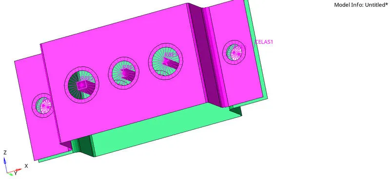
- APPLY MASS
- 1D >> MASSES >> SELECT NODE >> CREATE
- Apply mass of 10 kg at d and e point in both bracket
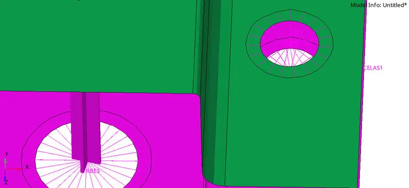
RESULT:
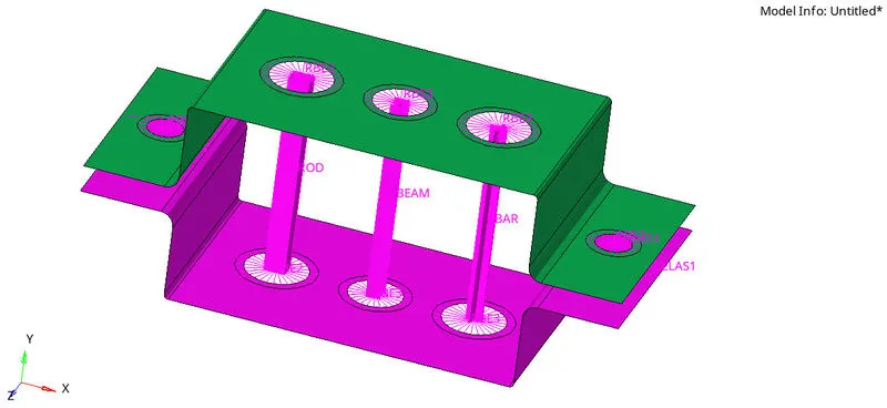
CONCLUSION :
- Created 1D elements on the given component with given cross-section and DOF.
- a-Rod element Created with only translational DOF and RBE2 link.
- b- Beam Element Created with all DOF and RBE3 link.
- c-Bar Element Created with only x&Y DOF and RBE3 link.
- d&e Mass added on the Master node of RBE2 link.
- f-Two Components were joined with Spring Elements.