Week 4-1D Element Creation Challenge
AIM
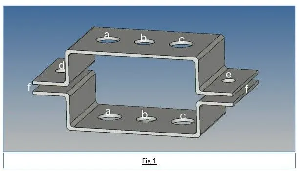
To mesh the given pair of brackets as shown in Fig 1 with 5units of size and to create 1-D element with the given cross-sections and with the prescribed DOF. The cross-sections are as follows:
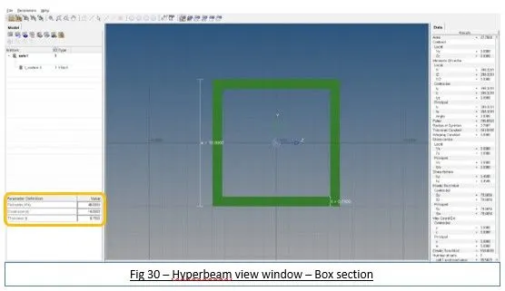
a. Rod element: - Translational DOF should be constrained with RBE2 link. Cross-Section: Box Section – Dimensions: a = 12; b = 10; t = 0.75
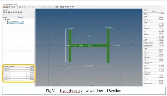
b. Beam element: - All DOF should be constrained with RBE3 link. Cross-Section: I Section – Dimensions: a =8; b = 10; c = 8.5; t1 = 0.75; t2 = t3 = 0.6
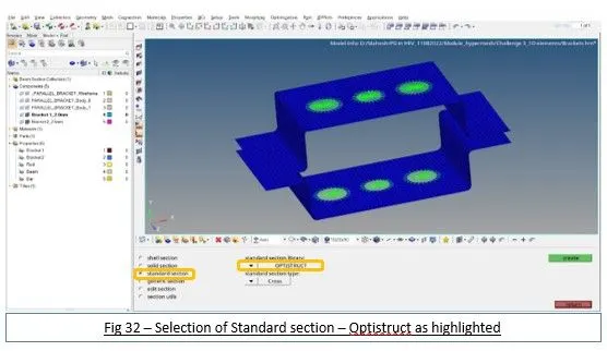
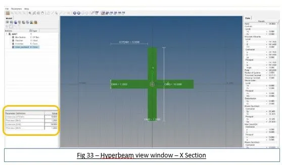
c. Bar element: - Only x and y DOFs constrained with RBE3 link. Cross-Section: X Section – Dimensions: Dim1 = 5; T. Dim2 = 1.2; Dim3 = 10; Dim4 = 1.2
(All above dimensions are in mm)
d & e. Magnitude of mass = 10 units applied to RBE2 link.
f. To join two brackets with spring elements
GIVEN
- Parallel bracket.IGS
- Dimensions for rod, beam and bar elements.
- Magnitude for mass.
OBJECTIVES
- To mesh the given parallel bracket with element size of 5units.
- To deploy bar, beam and rod elements in the prescribed positions as demanded in Fig1.
- To assign masses in the two highlighted RBE2 link and to deploy spring elements.
METHODOLOGY/PROCEDURE
1. Import the geometry:
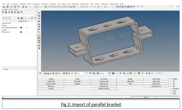
The given .igs model file will be imported into Hypermesh as shown in Fig2 in this process. Import geometry should be selected under the import panel. Analysis of the component to be carried out.
2. Deletion of unnecessary geometry:
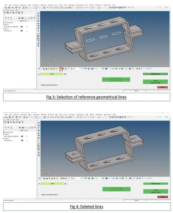
The reference geometrical lines are deleted in this process as shown in Fig 3 and 4. The delete command can be accessed as shown in Fig 3 – highlighted in red box.
3. Creation of Mid-surface:
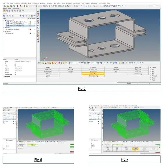
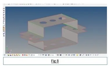
The mid-surface is created after deleting unnecessary entities. The mid-surface command can be accessed by Geometry ----> Midsurface, and is shown in Fig 5. Fig 6 shows the selection of surfaces of the parallel bracket to create mid-surface with auto-midsurface selection. To augment the quick selection of the entire component or the surface, the selection panel is used in which ‘by adjacent’ is selected as shown in Fig 7. And hit extract to create the mid-surface. The mid-surface of the component is shown in Fig 8.
4. Deploying washer:
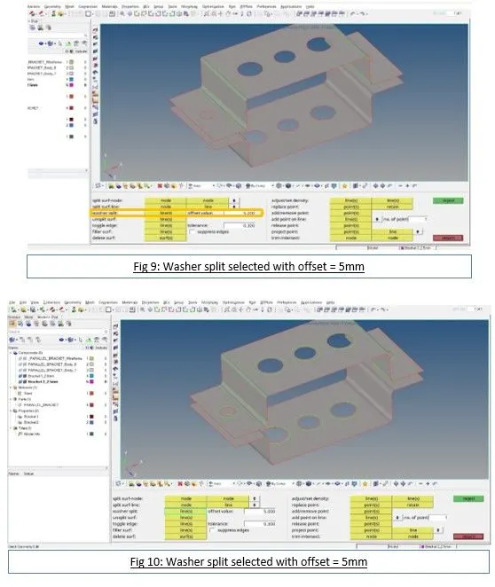
In order to have a uniform and even load distribution, washer is deployed in all the holes region. The command is ‘washer split’. To access this command, Geometry ----> Quick edit ----> Washer split ----> Line/perimeter of the hole selection. The result of deploying washer split is shown in Fig 10.
5. Assigning material and properties:
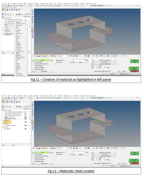
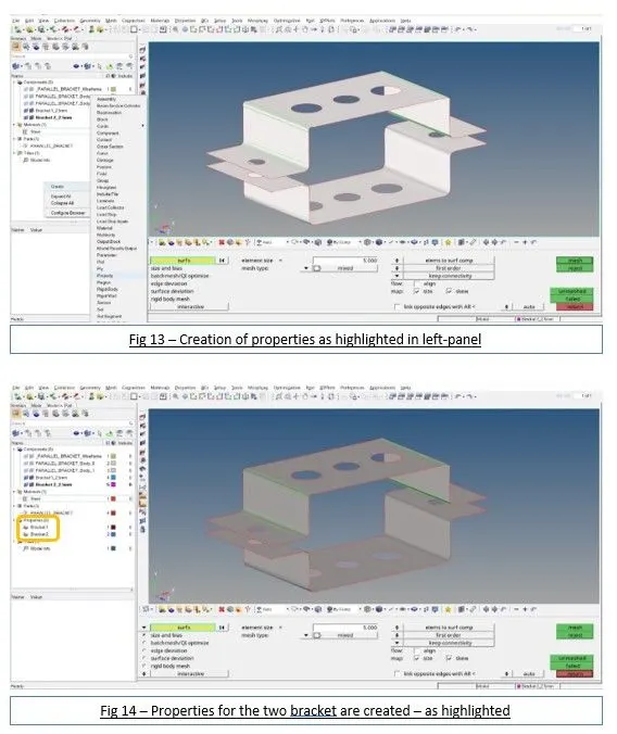
Before jumping into meshing, the materials and properties need to be assigned. So, this process involves assigning material and properties for the two brackets individually. The assigned material is steel, and the process involved are shown from Fig 11 to 16.
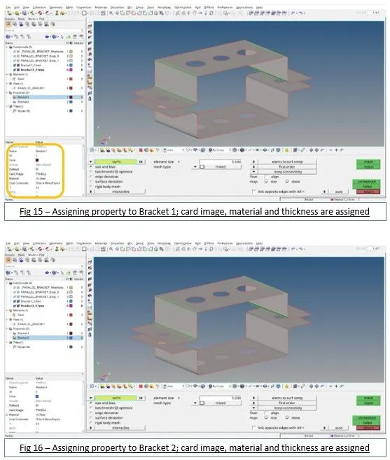
Now, the assigning of property Bracket1 is assigned to component Bracket1_2.0mm. This is carried out by selecting organize tool. The organize tool can be access by Tool ----> Organize ----> Select Surfs ----> Dest component = Bracket1_2.0mm and hit move. The explained procedure is shown in the Fig 17. The assigned properties will get moved to the component. The same process carried out for Bracket2_2.5mm with Bracket2 properties. The outcome of the above procedure is shown in Fig 18. And hit return.
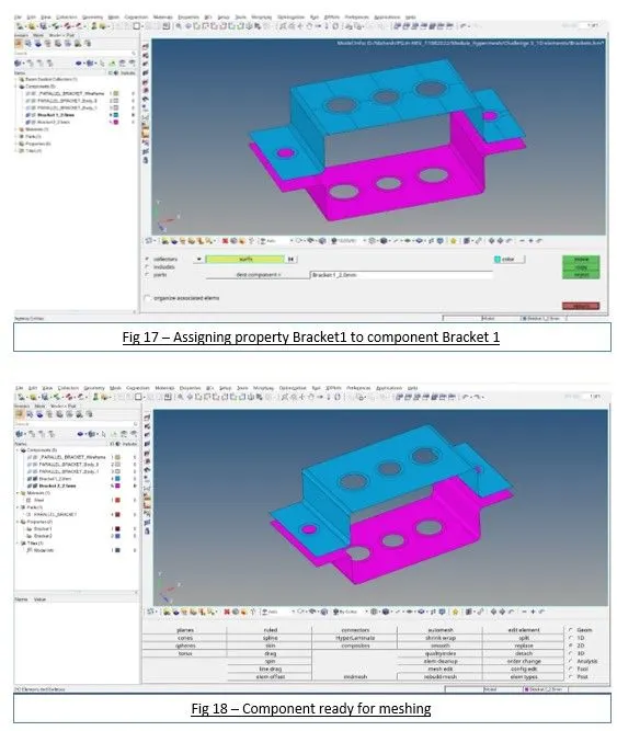
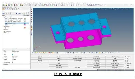
Before meshing, the surface of the component can be split to known uniform and even sizes as shown in Fig 19 in order to achieve good mesh flow. This can be done by splitting the surface with the tool ‘split-surf-line’. This tool can be accessed by Geometry ----> split-surf-line ----> Select node and then line. Surface split can be achieved.
6. Meshing:
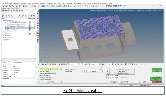
There are two ways to get the meshing done for the given component at this level. One is automesh and another is ruled. In order to use ruled mesh, either nodes or lines need to be present. So to try with the ruled mesh, the washer region are meshed with automesh. Automesh command can be accessed by 2D ----> Automesh ----> Surface selection, size & bias selection, mesh size = 5units, mesh type = mixed. ‘Hit mesh’ to mesh the surface as shown in Fig 20.
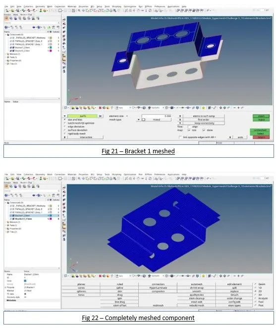
If necessary, ‘Rebuild Mesh’ can be used to get good mesh flow along with smooth option as well. The rebuild mesh can be accessed by 2D ----> Rebuild mesh ----> Elements selection. While smooth option will be available after hitting mesh under automesh or ruled mesh. Rest of the surfaces of the bracket1 also meshed with ruled mesh and is shown in Fig 21. Bracket2 also can be meshed following the same procedure as discussed above. And the completely meshed bracket1 & 2 component is shown in Fig 22.
7. Creating RBE2 and RBE3 links:
After meshing, the objective demands the creation of rod, beam and bar elements between the parallel brackets. For this purpose, the holes need to be assigned with links viz., RBE2 or RBE3 type.
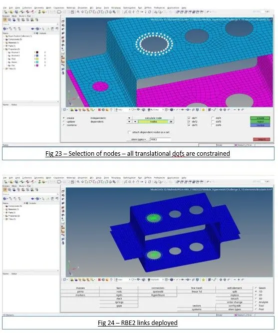
Assigning RBE2 – the RBE2 can be deployed by accessing rigids tool. This can be found by 1D ----> Rigids. The entire selection of nodes and assigning in bracket1 is shown in Fig 23. The same procedure should be followed for deploying RBE2 in bracket2 and the deployment of RBE2 links in both the brackets is shown in Fig 24.
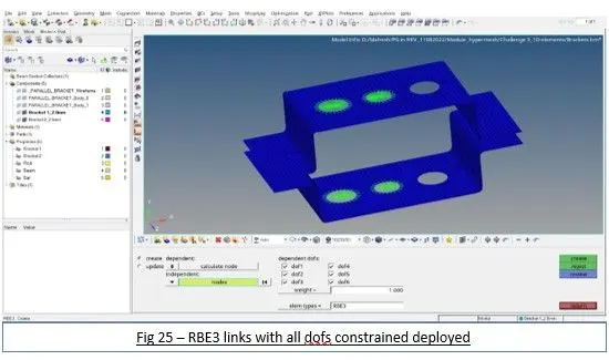
Assigning RBE3 with all DOFs constrained – the RBE3 can be deployed by accessing RBE3 tool. This can be found by 1D ----> RBE3. The entire selection of nodes and assigning with all DOFs constrained in bracket1 is shown in Fig 25. The same procedure should be followed for deploying RBE3 in bracket2.
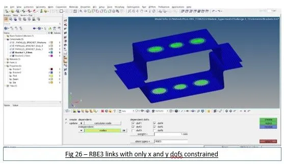
Assigning RBE3 with only x and y DOFs constrained –The selection of nodes and assigning with all DOFs constrained in bracket1 is shown in Fig 26. The same procedure should be followed for deploying RBE3 in bracket2.
8. Creating Hyperbeam elements:
After creating RBE2 and RBE3 links as per the prescription, it is time to create or link the two parallel brackets with the hyperbeam elements, viz., rod, beam and bar elements. The hyperbeam element and its associated cross-section can be assessed by 1D ----> Hyperbeam. The selection process of the above-mentioned elements are as follows:
a. Rod element: - Cross-section: Box
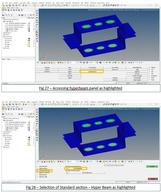
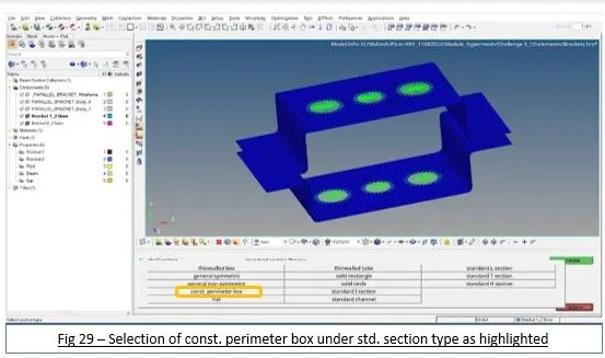
After following from Fig 27 to Fig 29, hit create. After hitting create, hyperbeam view window will be opened, where the selected cross-section will be displayed for editing the dimensional parameters purposes. This is shown in the Fig 30.
b. Beam element: - Cross-section: I-section
Follow the steps as shown in Fig 27 and 28. Then, in the section selection panel, select ‘standard I section’ and hit create. After hitting create, hyperbeam view window will be opened, where the selected cross-section will be displayed for editing the dimensional parameters purposes. This is shown in the Fig 31.
c. Bar element: - Cross-section: x-section
After accessing Hyperbeam as shown in Fig 27, select Optistruct instead of Hyperbeam in the ‘standard section library’. Then, in the section type selection panel, select ‘cross’ as shown in Fig 32 and hit create. After hitting create, hyperbeam view window will be opened, where the selected cross-section will be displayed for editing the dimensional parameters purposes. This is shown in the Fig 33.
9. Creating bar, beam and rod elements:
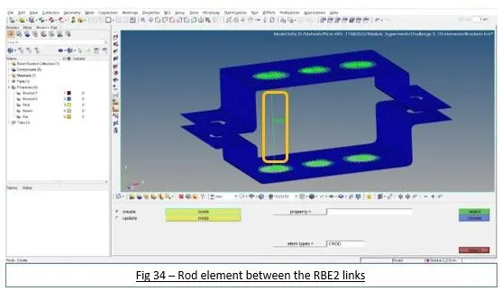
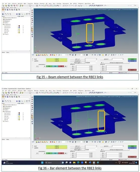
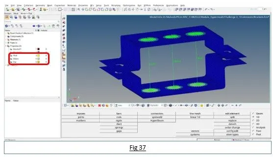
After creating the cross-sections, it is time to create the elements viz., bar, beam and rod that links the parallel brackets as shown in Fig 34, 35 and 36 respectively. And the command to access to create rod element is ‘Rods’ and it can be accessed by 1D ----> rods and the entire selection procedure is shown in Fig 34; while the command to access to create both beam and bar elements is ‘Bars’ and it can be accessed by 1D ----> bars and the entire selection procedure is shown in Fig 35 and Fig 36. Fig 37 shows the created three elements.
10. Creating and assigning properties for Hyperbeam/Optistruct elements:
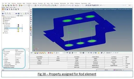
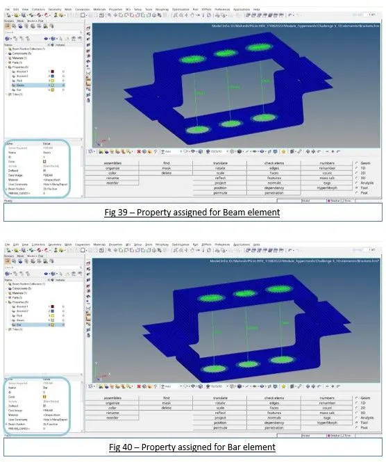
After creating the elements as shown in Fig 37, it is mandatory to create the properties for those elements respectively. The properties will be created under the already created property tab as highlighted(in Red) for each individual elements as shown in Fig 37. The assigning of properties(highlighted in light blue) for each elements is shown from Fig 38 to Fig 40.
11. Creating RBE2 element and assigning masses:
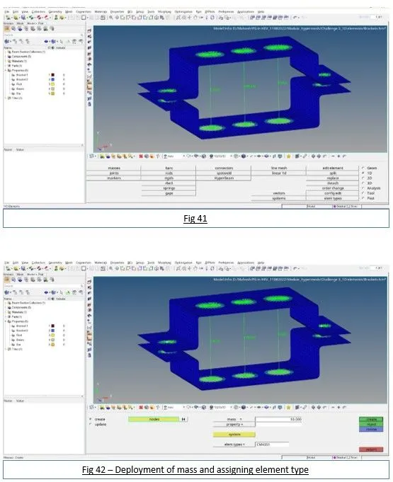
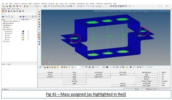
RBE2 elements are created at the pair of collar of the both the brackets as shown in Fig 41. Then mass element assigned to the created RBE2 link with mass deployment of 10units as shown in Fig 42 and 43.
12. Deployment of Spring element: -
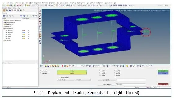
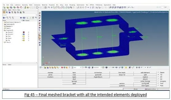
As per the aim of the project, spring element is deployed at all corners of the given pair of brackets. Fig 44 depicts the method of creating a spring element at one of the corner, the same procedure is followed to create the spring elements at the rest of three corners. Fig 45 depicts the complete deployment of all rigid links and elements.
Conclusion
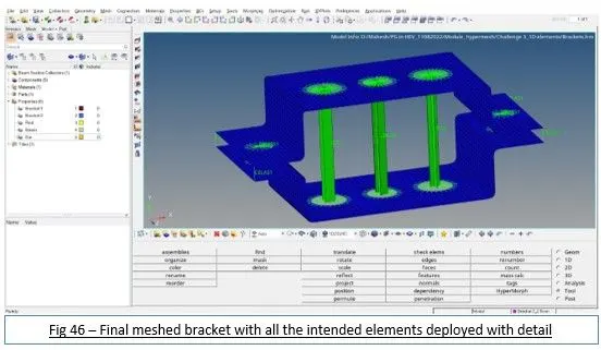
Hence, the given pair of brackets are meshed with 5units of size after taking mid-surface; and 1-D element with the given cross-sections and with the prescribed DOF are created. With the independent node of RBE2 links located at the collars of the pair of brackets are assigned with mass of value = 10units. And the pair of brackets are connected with spring elements. The final detailed depiction of the project is shown in the Fig 46 below:
Learning Outcome
- Hands on experience on Hypermesh or hyperwork tool.
- Attained valuable knowledge about FEA in detail with example; and with the challenge project.
- Gained knowledge about extracting mid-surface, meshing and editing the mesh.
- Obtained knowledge about how to assign links and elements.