Week 4-1D Element Creation Challenge
OBJECTIVE:- Take a mid surface & mesh the given component & create 1d element on the following component with given cross-section and DOF.
a. Rod element:- Translational DOF should be Constrained with RBE2 link
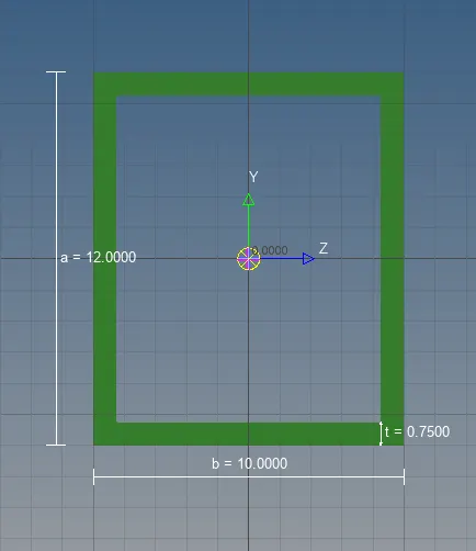
Cross-Section: BOX- Dimension a= 12 mm
dimension b=10 mm
Thickness t= 0.75 mm
b. Beam element:- All DOF should be constrained with RBE3 link
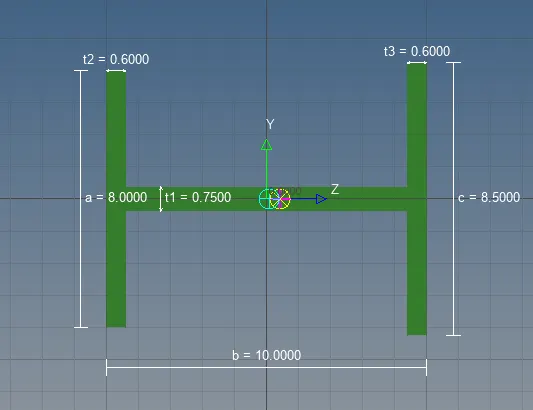
Cross-Section: I Section- Dimension a= 8 mm
Dimension b= 10 mm
Dimension c= 8.5 mm
Thickness t1= 0.75 mm
Thickness t2= .6 mm
Thickness t3= .6 mm
c. Bar element:- Constrain only x and y DOFs With RBE3 link
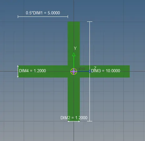
Cross-section: X section- Dimension DIM1= 5 mm
Thickness DIM2= 1.2 mm
Dimension DIM3= 10 mm
Thickness DIM4= 1.2mm
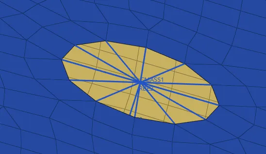
d. & e. Apply the mass of magnitude 10 with the RBE2 link
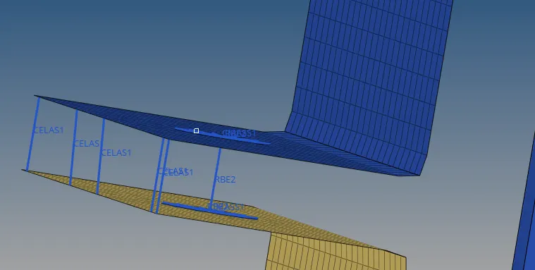
f. Join the two components with Spring elements
PROCEDURE:
- Import the model by using geometry option in the form of IGES format and delete the wireframe.
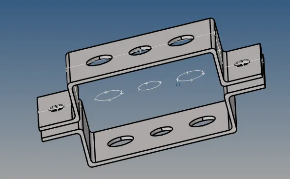
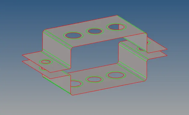
Creating the mid surface for the given component
- As the thickness of the given component is uniform, Select the component and create a mid surface for the top component (bracket 1) by making it current selection and select OFFSET method for midsurface.
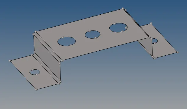
-
Select the component and create a mid surface for the bottom component (bracket 2) by making its current selection, select OFFSET method for midsurface.
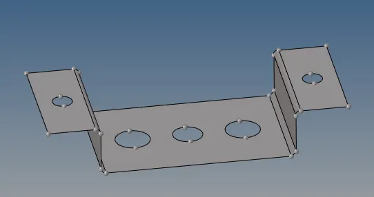
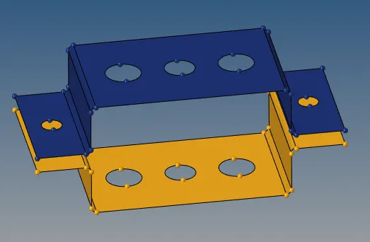
- Then we assign the Material & properties to the midsurface component in the model browser.
Create Material:-
- We select steel as the Material for this component.
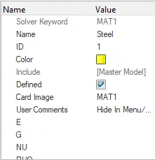
Creating the properties:-
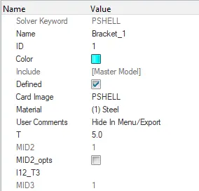
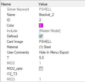
Meshing the component:-
- To mesh the given component, we need to create washer splits near the hole region for a smooth mesh. Washer split offset we selected is 5mm.
- Generate the mesh with element size as 5mm with mixed element type.
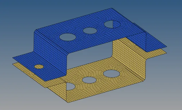
Create the rigid at points a,b,c & d:-
- Create the RBE2 and RBE3 at the respective holes with the given DOF.
- We create RBE2 elements using rigids in 1D module for the first holes in top & bottom & we restrict the element to transitional DOF in X,Y & Z axis as mentioned for the first case. similarly for case 2 and case 3.
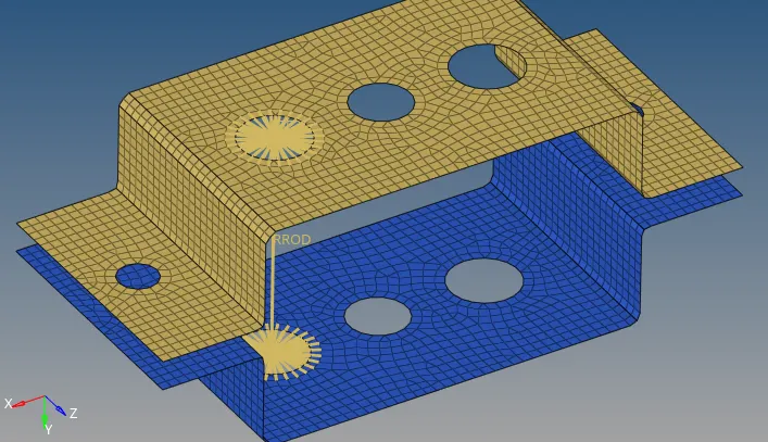
- We create RBE3 elements using rigids in 1D module for the first holes in top & bottom & we restrict the element to all DOF in X,Y & Z axis as mentioned for the second case.
- At last created RBE3 elements using rigids in 1D module for the first holes in top & bottom & restricticting the element to all DOF in X & Y axis as mentioned for the third case.
- Hence after creating RBE2 & RBE3 elements, creating the rod, bar and beam 1D elements at the respective node points.
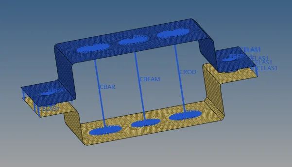
- Once RBE2 & RBE3 created, we should create mass with the magnitude of 10 & type of mass should be given as CMASS1 for case d & e.
Creating cross sections for Rod, Bar & Beam:-
- To create the 1D element, we need to go the hyper beam tool and select the respective cross-section for creating the 1D element and give the assigned dimension to the geometry as mentioned in the specification.
- creating cross sections for the ROD in the form of thin wall box which has been given for the first case.
- Creating cross section for the BEAM in the form of I-section which has been given for the second case.
- Creating cross sections for the BAR in the form of Cross-section which has been given for the third case.
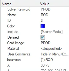
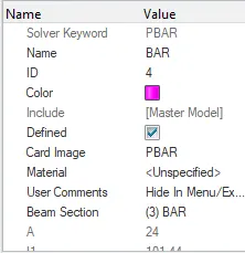
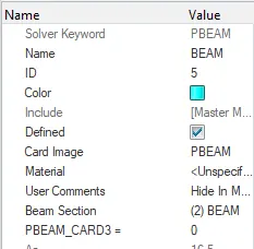
- Once cross sections are created, we need to create property for Rod, Beam, Bar with property cards such as PROD, PBEAM, PBAR.
- Mass is applied with the magnitude of 10 in RBE2 & spring elements are joined as been mentioned.
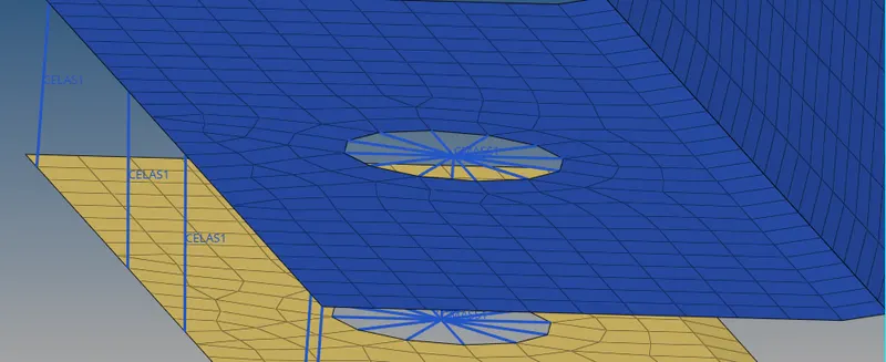
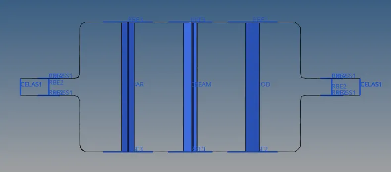
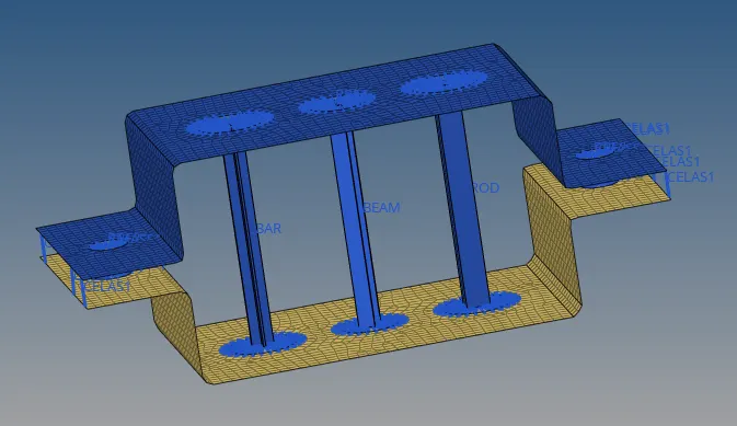
2-D element detailed representation:
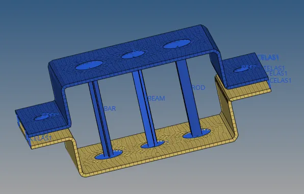
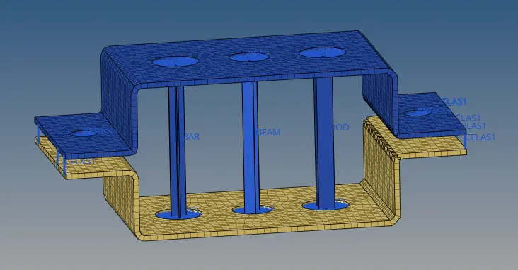
Conclusion:-
- Extracted the mid-surface for the given component and Created a Mesh on the mid-surface.
- Deployed suitable 1D Element ( RBE2, RBE3, ROD, BAR, BEAM , MASS, SPRING etc ) to the respective places.
- Assigned Cross-section and property to the 1D elements.
- Created Solid representations of 1D Element.