To Become Familiar with 1D Elements Of Hypermesh
1. AIM: To Become familiar with 1D elements of Hypermesh.
2. OBJECTIVE OF THE PROJECT :
- Mesh the Given component with the Size of 5 Units.
- Create 1D elements on the following component with a given cross-section and DOF.
- Rod element:- Translational DOF should be Constrained with RBE2 link
Cross-Section: BOX
Dimension a= 12 mm, b=10 mm, t= 0.75 mm - Beam element:- All DOF should be constrained with RBE3 link
Cross-Section: I Section
Dimension a= 8 mm, b= 10 mm, c= 8.5 mm, t1= 0.75 mm, t2= .6 mm, t3= .6 mm - Bar element:- Constrain only x and y DOFs With RBE3 link
Cross-section: X section
Dimension DIM1 = 5 mm
Thickness DIM2 = 1.2 mm
Dimension DIM3 = 10 mm
Thickness DIM4 = 1.2mm - Apply the mass of magnitude 10 with the RBE2 link (for d & e locations)
- Join the two components with Spring elements (at f locations)
- Rod element:- Translational DOF should be Constrained with RBE2 link
3. BODY OF CONTENT :
A. Mesh the Given component with the Size of 5 Units
As per the rule, if the thickness of the part is less then or equal to 6mm, then we should go with 2D mesh. So, a Mid-mesh generated (using Midsurfaces: Auto Extraction). And applied 'Auto Geometry Cleanup' as per the given quality area of 5 units.
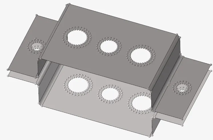
Image: 01 Model after 'Auto geometry cleanup'
Now A mesh is generated, Using a '2D: Automesh' & rebuilded & smoothing done via 'smooth' & 'rebuild mesh' option.
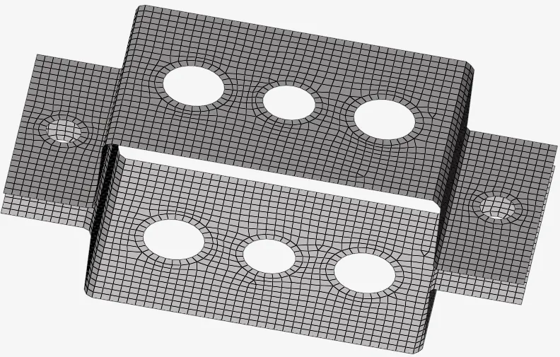
Image: 02 Meshed Part
B. Creating a 1D elements with given cross-section and DOF
a. Rod element:- Cross-Section: BOX
This is a holo BOX, where a,b & t is given, So using a (1D > HyperBeam > standard section > HYPERBEAM library > thinwalled box) cross section is created (can see in below image). As stated, "Translational DOF should be Constrained with RBE2 link". So, created a two RBE2 cluster at point 'a'. Where 123 dof is constrained. Then A 'CROD' element is created with a properties, its Cross-Section (BOX) and elem types (CROD).
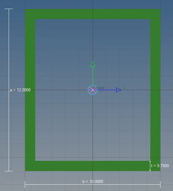
Image:03 Rod Element
b. Beam element: - Cross-Section: I-Section
This is a standard type I-Section. Using a (1D > HyperBeam > standard section > HYPERBEAM library > standard I section) a cross section is created (can see in below image). As stated, "All DOF should be constrained with RBE3 link". So, created a two RBE3 cluster at point 'b'. Where 123456 dof is constrained. Then A 'bars' element is created with a property, its Cross-Section (I-Section) and element type (CBEAM).
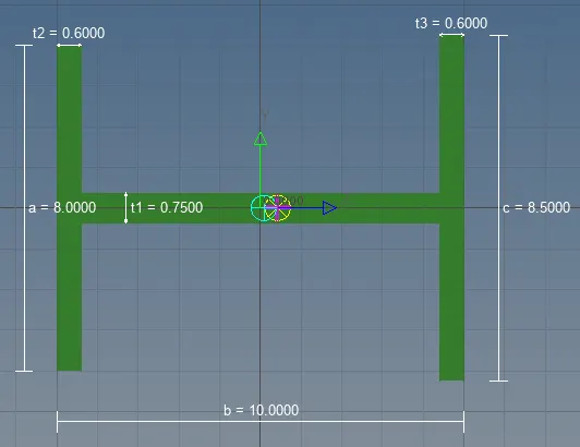
Image: 04 Beam Element
c. Bar element: - Cross-section: X section
This is a '+' or 'x' cross-Section. Using a (1D > HyperBeam > standard section > OPTISTRUCT library > 'Cross' section type) a cross section is created (can see in below image). As stated, "Constrain only 'x' and 'y' DOFs With RBE3 link". So, created a two RBE3 cluster at point 'c'. Where 1245 dof is constrained. Then A 'bars' element is created with a property, its Cross-Section (cross-Section) and element type (CBAR).
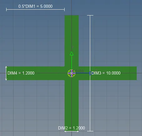
Image: 05 Bar Element
d. Apply the Mass of magnitude 10 with the RBE2 link:
Here Mass is a rigid element. So, here it is defined by RBE2 elements. Now, Using a (masses > Create) element created. where, mass = 10, Property ID created with name 'mass', element type - CONM2 applied.
f. Join the two components with Spring elements:
It’s a simple two node element. It’s a one type of elastic element. Which has the properties of spring. So, Using a (Springs > Create) element is created.
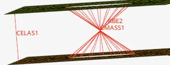
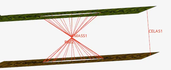
Image: 06 CMASS & CELAS element
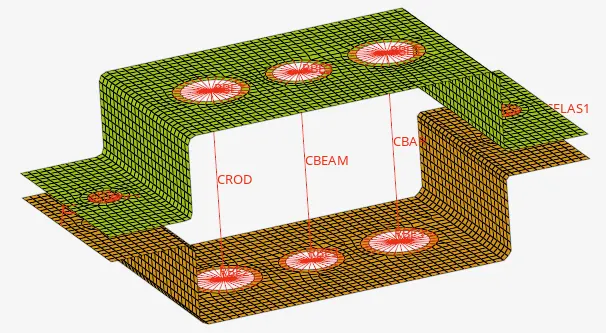
Image: 07 Final Model
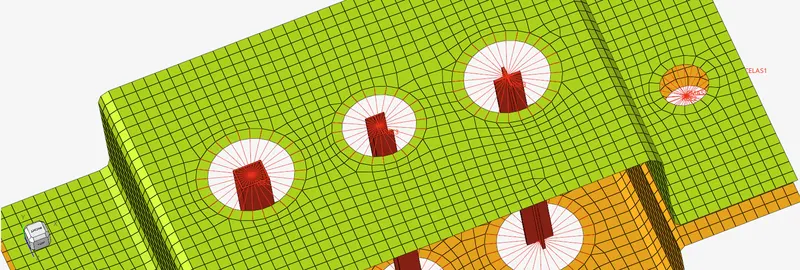
Image: 08 Model with Enabled display of elements
4. CONCLUSION :
In this challenge, I got familiar with how to use 1D elements in Hypermesh, How to define a Degree of Freedom, Its properties, How to update the elements that were created before and many...