Week 4-1D Element Creation Challenge
To Mesh the given components with the size of 5 units and to
create 1D elements on the following components with the given
cross - section and DOF.
GIVEN DATA :-
a. Rod element:- Translational DOF should be Constrained with RBE2 link
Cross-Section: BOX- Dimension a= 12 mm
dimension b=10 mm
Thickness t= 0.75 mm
b. Beam element:- All DOF should be constrained with RBE3 link
Cross-Section: I Section- Dimension a= 8 mm
Dimension b= 10 mm
Dimension c= 8.5 mm
Thickness t1= 0.75 mm
Thickness t2= 0.6 mm
Thickness t3= 0.6 mm
c. Bar element:- Constrain only x and y DOFs With RBE3 link
Cross-section: X section- Dimension DIM1= 5 mm
Thickness DIM2= 1.2 mm
Dimension DIM3= 10 mm
Thickness DIM4= 1.2mm
d. & e. Apply the mass of magnitude 10 with the RBE2 link
f. Join the two components with Spring elements
PROCEDURE :-
The aim is to create 1D elements in the given model. The model
consist of two brackets with circular holes. The element type, cross
section geometry, dimensions and positions are defined in the problem
statements.
Firstly, the given 3D model of the bracket is imported in to the workspace.
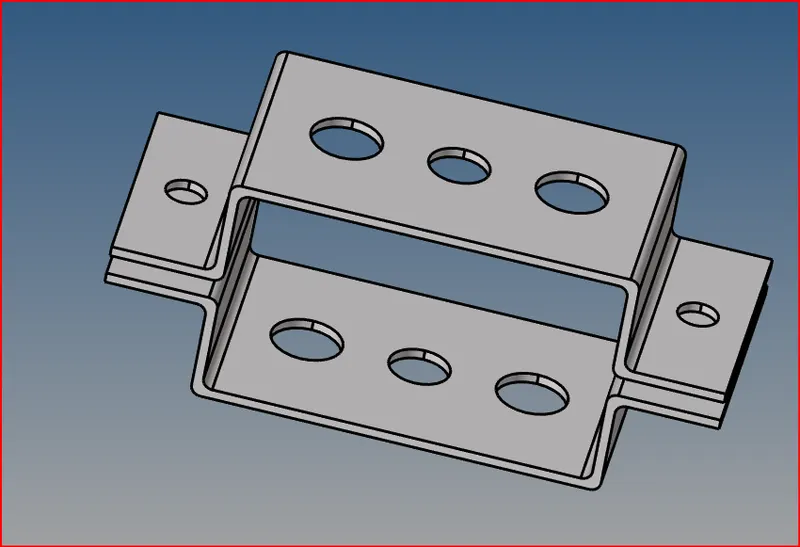
fig. Imported Model
Before creating the elements, we generate the midsurface of the components.
The midsurface option can be found in the geometry tab. In this option select
skin offset option in the extraction options. Select the surface option in auto
extraction, define the surface from which the mid surface is to be generated
and press the extract button.
Geom >> Midsurface >> Surf >> Auto midsurface >> Extract
The Create a new component in the model tree and create the midsurface for
the another component. Assign this newly created midsurface to the component
using move in organize option in tool tab. After that the we got the generated mid
surface.
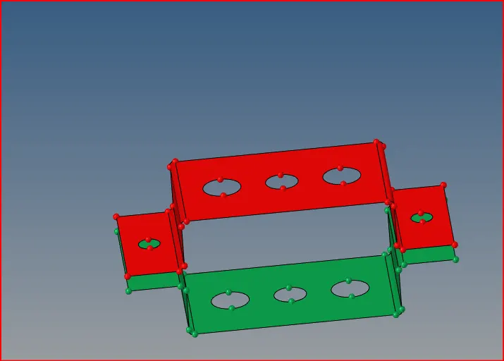
fig. Mid surface and used move option
After that, cretaed washer split around the circular hole feature in the components.
This can be done in quick edit in the geometry tab. This dist was set as 5 mm.
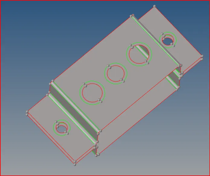
fig. washer created
After that create a 2D mesh in the components with element size as 5mm. This can be
carried out in automesh option in 2D tab. The element type was set as mixed. To create
a finer mesh along the circular region, increase the number of nodes by clicking the left
button on the nod value.
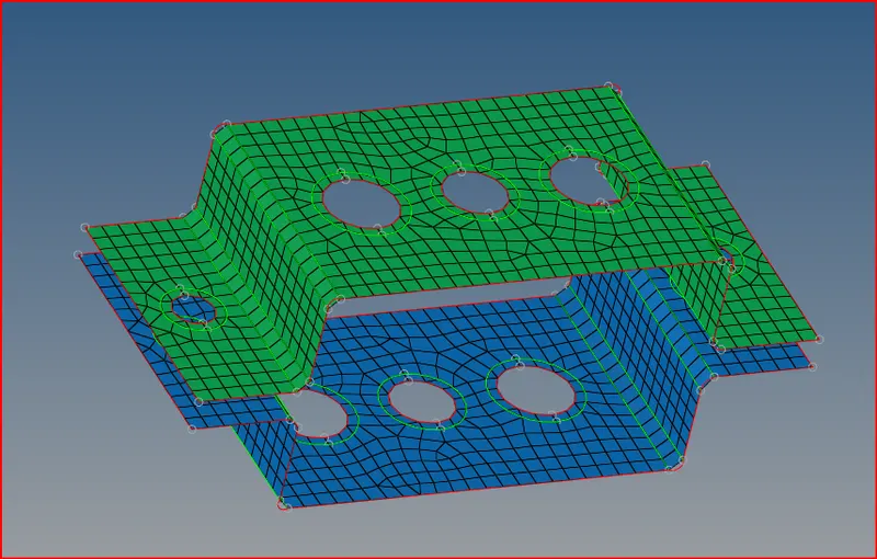
fig. Created mesh
Then, steel material was created and was assigned to both the components.
After that, properties for both bracket components were created and assigned.
Then, Cross sections are defined in the problem statement were created using the
hyperbeam tool. Three sections were created namely box, I and cross section were
created with dimensions as a given in the problem.
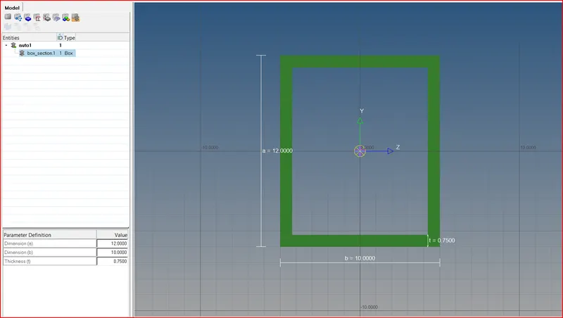
fig. Box Section
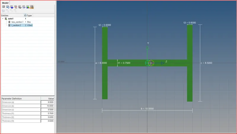
fig. I section
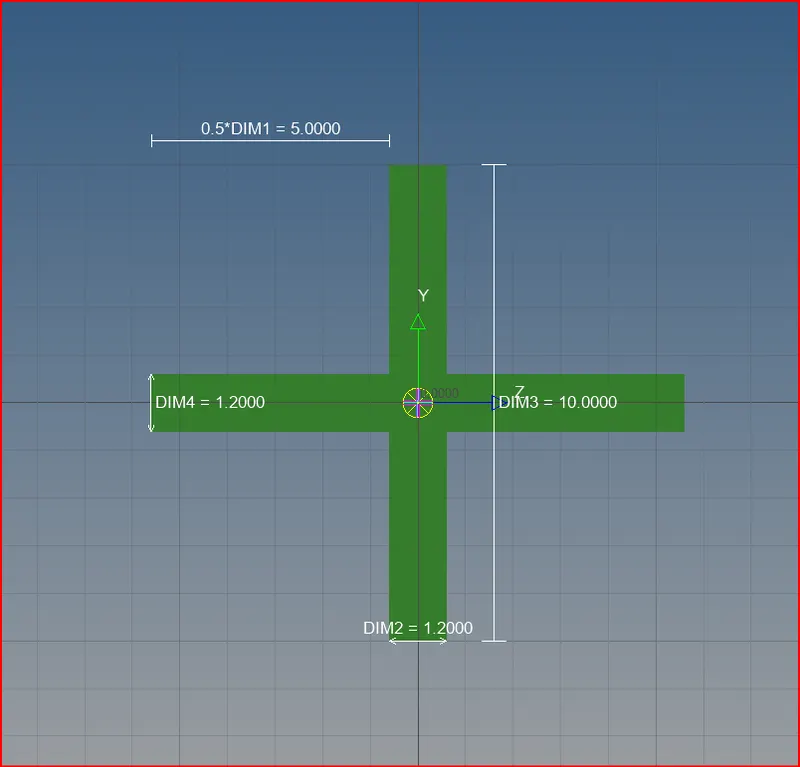
fig. Cross section
Under the properties sectionin the model tree, properties were defined for
the rod, bar and beam were defined.
Then create the links, the nodes along the circular feature were selected
and the RBE2 and RBE3 links were created.
The rod, bar and beam elements were created by selecting the centre nodes in
the appropriate links. The DOF's were defined as specified in the problem
statement. To create the elements, go to 1D tab, select element type and
define the nodes.
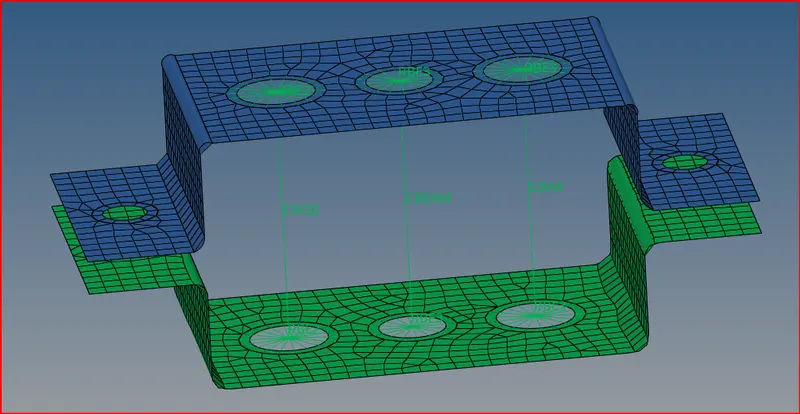
fig. 1D
For each of the elements created, the appropriate cross section as defined in the
problem statements were assigned from the properties section.
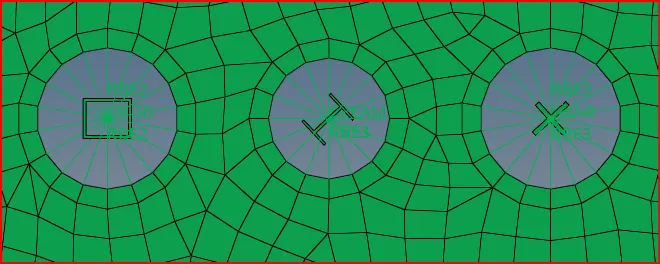
fig. cross section of top view
After that, create the mass elements, the RBE2 links were created at the required
points. To assign the mass, go to 1D tab and select the mass, select the node, define the mass
value and create the element.
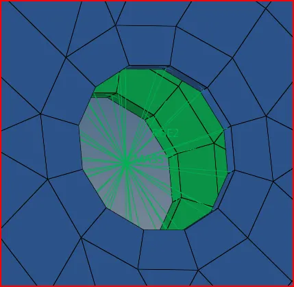
fig. RBE2 with mass
After that, we created spring elements. Go to 1D tab, select the
spring elements and then define the nodes between which the
element has to be created and press create button.
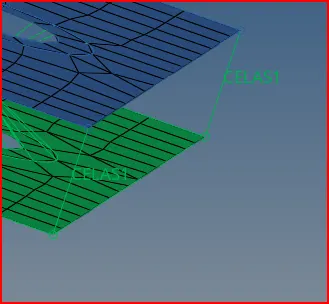
fig. spring
The final model after creating all the elements as defined
in the problem statement as as follows :-
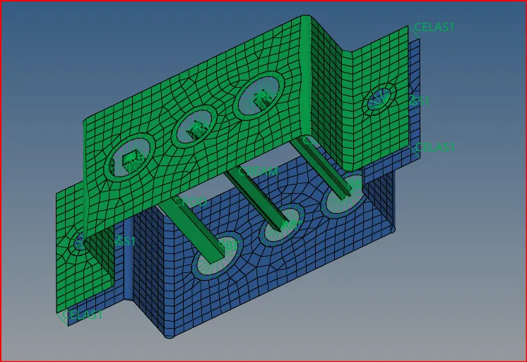
fig. 1D
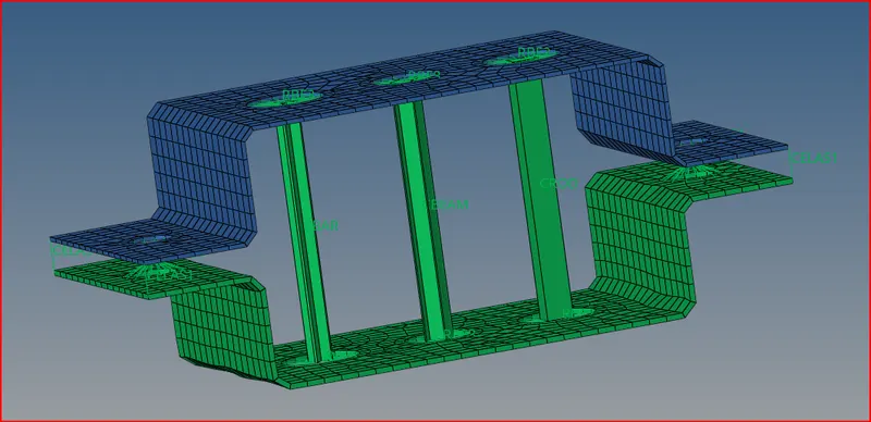
fig. 2D (FINAL IMAGE)
CONCLUSION :-
The mid surface were created fo the given components and the
2D mesh was generated.
Bar, Rod, Beam, Mass and Spring elements were created in the model.
RBE2 and RBE3 links were created at the specified holes.
Different cross sections were created using the Hyperbeam tool and
was assigned for the appropriate elements.