Week 4-1D Element Creation Challenge
Aim:
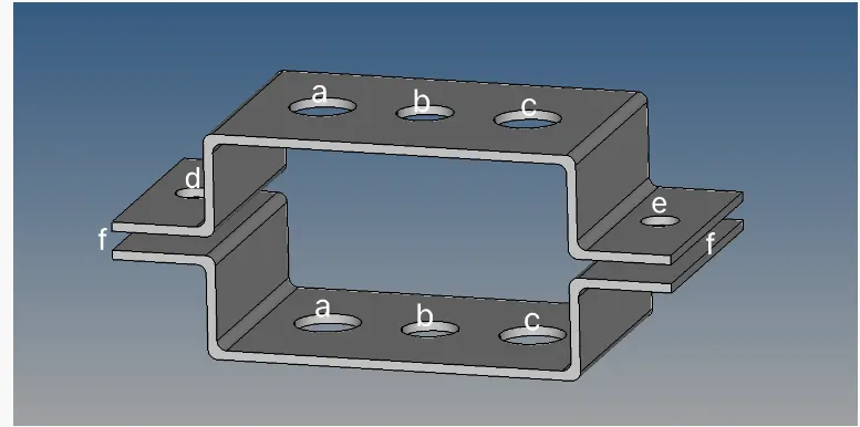
Mesh the Given component with the Size of 5 Units. Create 1D elements on the following component with the given cross-section and DOF
a. Rod element:- Translational DOF should be Constrained with the RBE2 link
Cross-Section: BOX- Dimension a= 12 mm
dimension b=10 mm
Thickness t= 0.75 mm
b. Beam element:- All DOF should be constrained with the RBE3 link
Cross-Section: I Section- Dimension a= 8 mm
Dimension b= 10 mm
Dimension c= 8.5 mm
Thickness t1= 0.75 mm
Thickness t2= .6 mm
Thickness t3= .6 mm
c. Bar element:- Constrain only x and y DOFs With the RBE3 link
Cross-section: X section- Dimension DIM1= 5 mm
Thickness DIM2= 1.2 mm
Dimension DIM3= 10 mm
Thickness DIM4= 1.2mm
d. & e. Apply the mass of magnitude 10 with the RBE2 link
f. Join the two components with Spring elements
Procedure:
Import the model into the Software. Since the file is in IGES format click the IGES in the format window
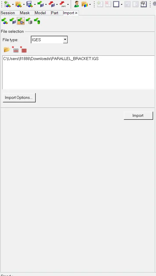
Click import and the model is imported into the Database
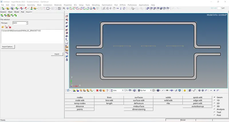
Material has to be assigned as steel.
Before Meshing and connections can be made Mid surface of the component has to be done.
This can be done using GEO>Midsurface, On selecting the Model Click Extract, and Midsurface is generated
Assign the Midsurface with Pshell as ID and Thickness as 5. Property is Assigned to both surfaces
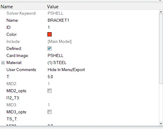
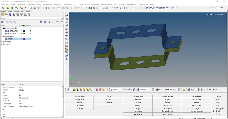
Once the Midsurface is done and Property has been assigned. Meshing is done
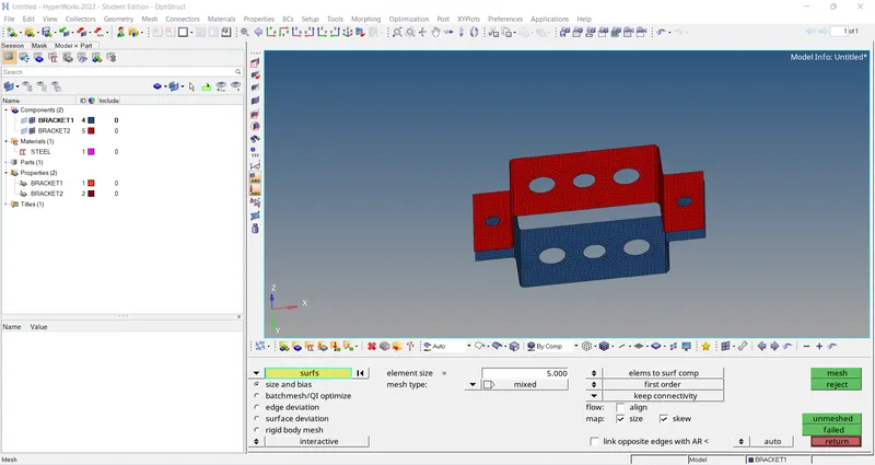
2D>Automesh
Assign elements size as 5
Mesh type: Mixed
Click on MESH
RBE2 and RBE3 connections are done with their respective DOFS
For ROD Translational DOF should be Constrained with the RBE2 link
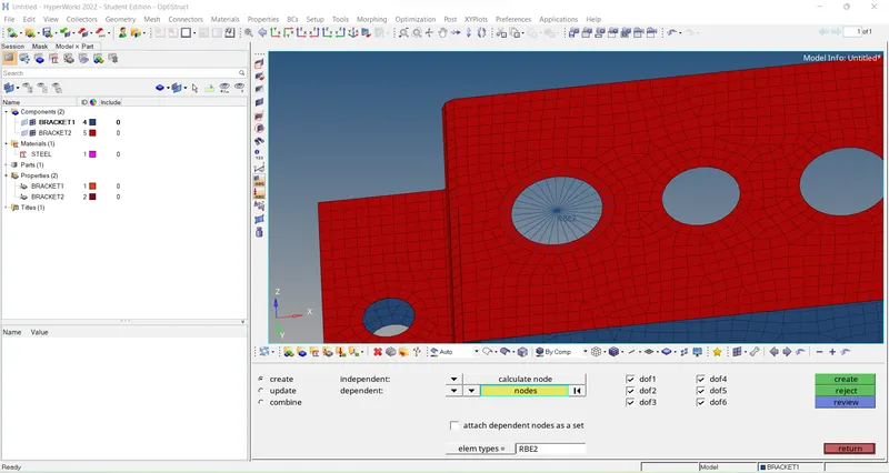
For BEAM All DOF should be constrained with the RBE3 link
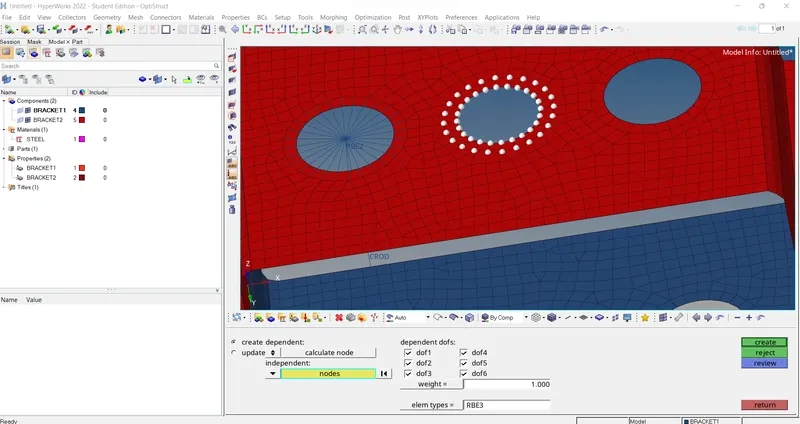
For BAR elements Constrain only x and y DOFs With the RBE3 link
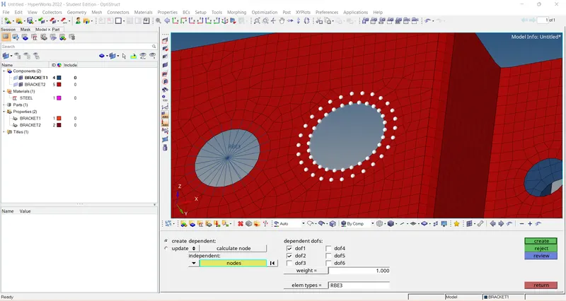
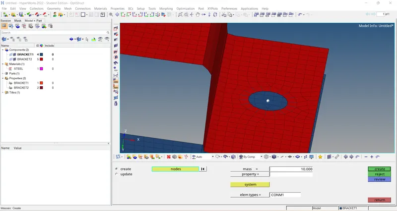
For d. & e Shown in the drawing. A mass of magnitude 10 with the RBE2 link is applied
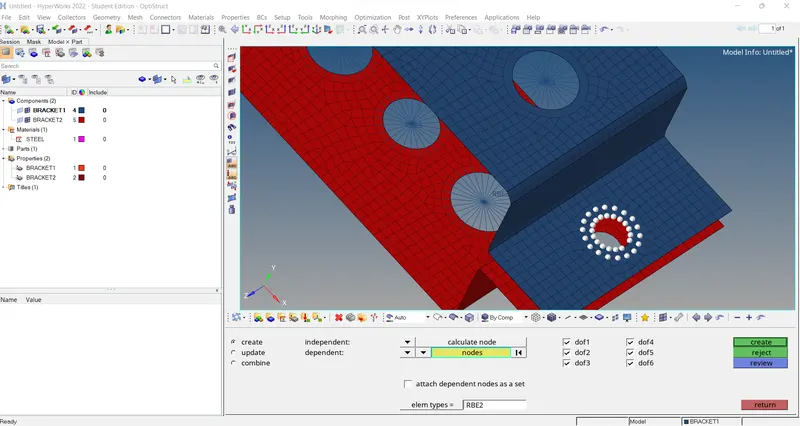
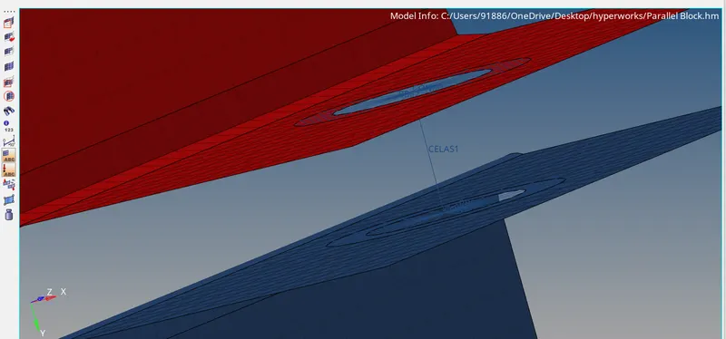
for f shown on the drawing. the components are connected with spring elements
1D>Springs, Select the two RBE2
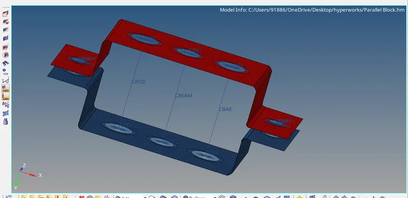
1D such as BAR, ROD, and Beam has to be deployed with hyper beam used has crossection
1D elements such as ROD, BAR, and Beam are created using 1D>(BAR, ROD, BEAM)
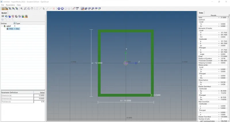
Cross-sections are created using Hyperbeam options and necessary dimensions are given
For ROD
Cross-Section: BOX- Dimension a= 12 mm
dimension b=10 mm
Thickness t= 0.75 mm
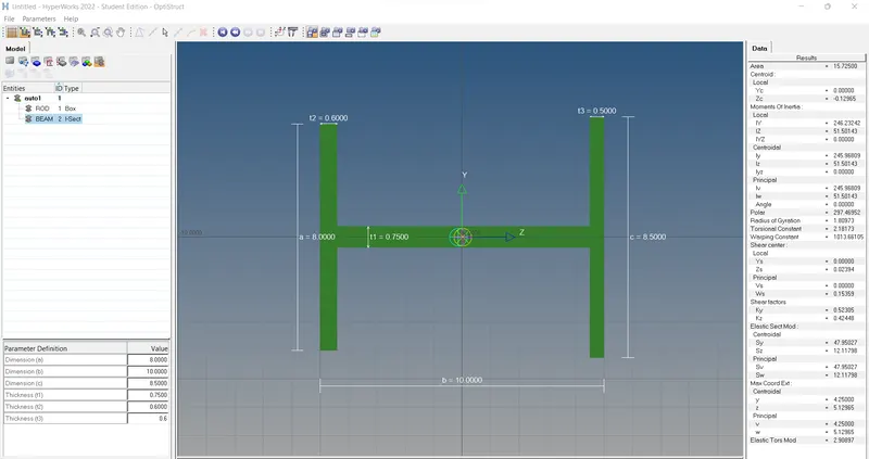
For Beam element:
Cross-Section: I Section- Dimension a= 8 mm
Dimension b= 10 mm
Dimension c= 8.5 mm
Thickness t1= 0.75 mm
Thickness t2= .6 mm
Thickness t3= .6 mm
For BAR element:
Cross-section: X section- Dimension DIM1= 5 mm
Thickness DIM2= 1.2 mm
Dimension DIM3= 10 mm
Thickness DIM4= 1.2mm
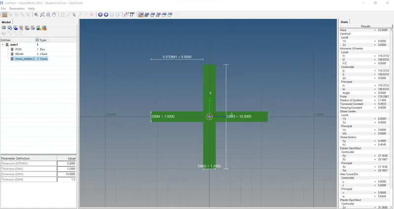
After creating the Crosssection Separate property has to be assigned to each bar, rod, and beam element
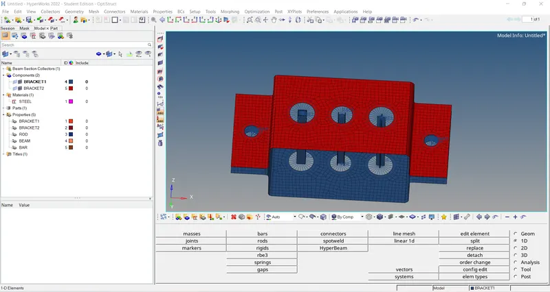
FInal Model