Week 4-1D Element Creation Challenge
1D Element Creation Challenge
AIM:
- To Deploy the 1D element connection in the given model using Hyperworks pre-processor
OBJECTIVE:
- Mesh the Given component with the Size of 5 Units. Create 1D elements on the following component with given cross-section and DOF.
PROCEDURE:
IMPORTING THE MODEL
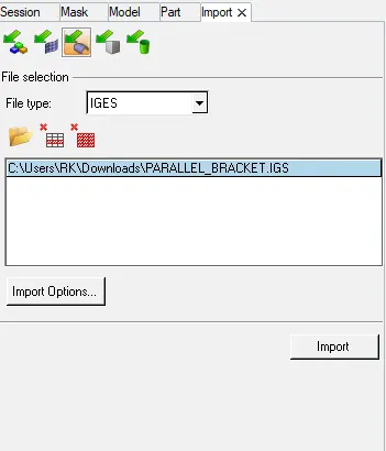
- The given model is in IGES file format
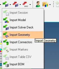
- To open it, Go to --> Import file --> Import geometry --> file session window --> Choose file --> Import
- The file is imported to the Graphical window.
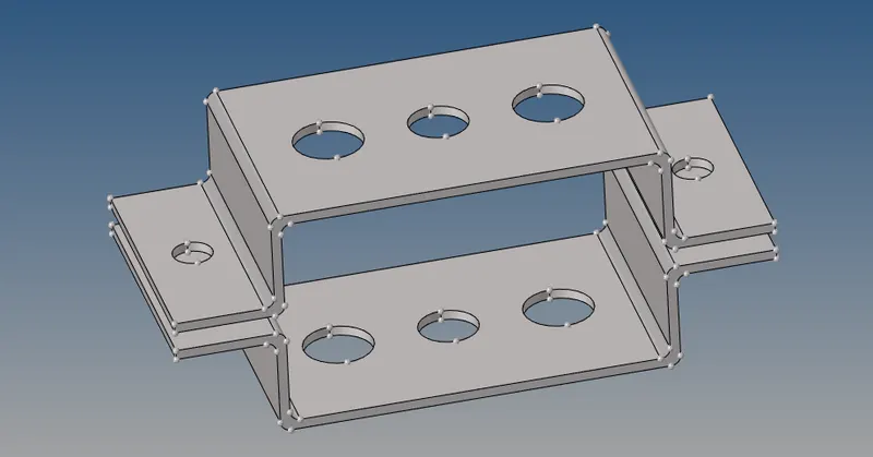
figure - Given model
EXTRACTING THE MID SURFACE
- We can extract the mid surface using (Main menu --> Geometry page --> mid surface --> auto midsurface --> skin offset)
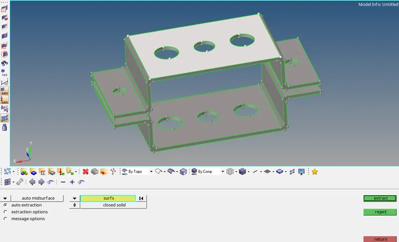
figure - Mid surface using auto midsurface option
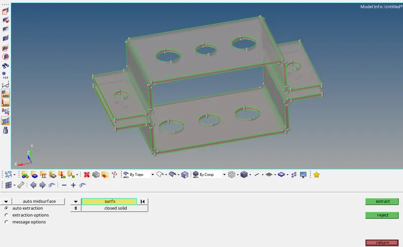
figure - Extracted mid.surface
- Mid is the neutral pahse which is been generated from the CAD which is imported or given to us.
- The conversion of 3D cad to 2D cad is happening in mid surface generation.
- The mid surface is generated to reduce the complexity as by simplifying the cad model we get more accurate simulation results in shorter time.
ASSING PROPERTY TO THE COMPONENTS
- We can create new components in the MODEL TAB
- (Tab area --> Click on white space --> create -->Components/Parts)
- The below pictures shows that we can chose from there what ever we want to create in new and assign them with components.
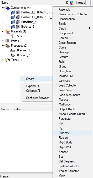
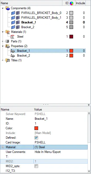
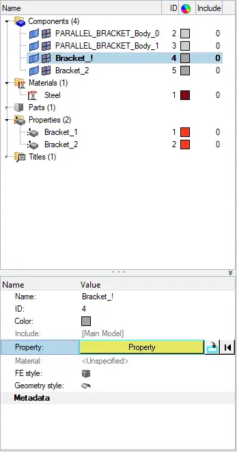
figure - New property creation
WASHER CREATION AROUND THE HOLES
- Creating the washer area is useful to capture the proper mesh flow near the hole areas.
- Go to --> main menu --> geom page --> quick edit --> washer split
- In this model I setup the offset value as 5mm, because of target element for meshing also 5mm
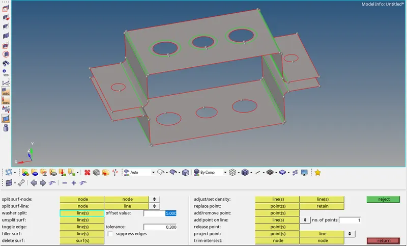
figure - washer split
MESHING
- Meshing can be done using (main menu --> 2d page --> automesh)
- Setup the given target element size as 5mm, click on Mesh
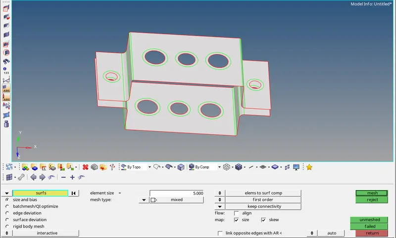
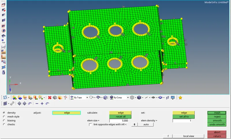
figure - Meshed component
DEPLOYING NECESSORY CONNECTIONS
- Here in this model RBE2 and RBE3 link types used to make connections
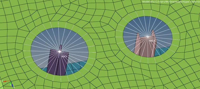
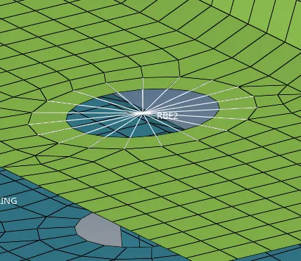
figure - RBE2 & RBE3 cluster
- RBE2 - The given load/force will equally distributed to the other nodes, this is a strong Rigid connection
- RBE3 - The given load/force will not be equally distributed to the other nodes. It will be reduced by distance and type of material used.
VARIOUS CONNECTIONS
- We can make connection using (main menu --> 1D page --> bars/rods/rigids/masses/springs/rbe3)
- These connection are shown below.
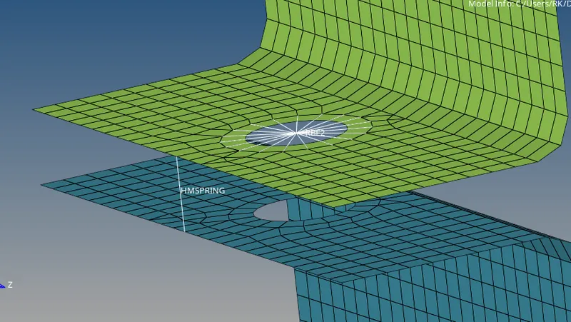
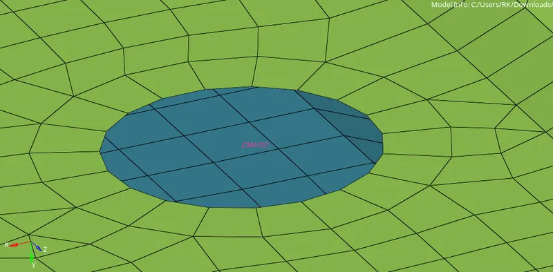
- MASS and SPRING connection has delployed in the necessary areas as by requirments.
CROSS SECTION WITH PROPER DOF GIVEN DATA
a. Rod element:- Translational DOF should be Constrained with RBE2 link
Cross-Section: BOX- Dimension a= 12 mm
dimension b=10 mm
Thickness t= 0.75 mm
b. Beam element:- All DOF should be constrained with RBE3 link
Cross-Section: I Section- Dimension a= 8 mm
Dimension b= 10 mm
Dimension c= 8.5 mm
Thickness t1= 0.75 mm
Thickness t2= .6 mm
Thickness t3= .6 mm
c. Bar element:- Constrain only x and y DOFs With RBE3 link
Cross-section: X section- Dimension DIM1= 5 mm
Thickness DIM2= 1.2 mm
Dimension DIM3= 10 mm
Thickness DIM4= 1.2mm
d. & e. Apply the mass of magnitude 10 with the RBE2 link
f. Join the two components with Spring elements
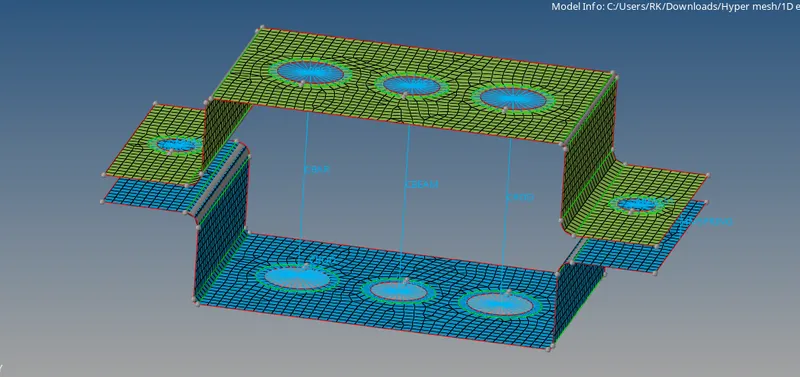
- CBAR, CBEAM, CROD connection has been deployed as per the requirments
HYPER BEAM VIEW ENTITIES CREATION
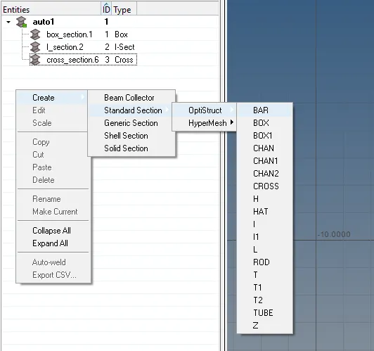
- We can easily create cross section elements by using (Go to --> Hyper beam tap --> click on white area --> create --> standard section/generic section --> optistruct/hypermesh --> click anything we want)
- Here we created Box section, I-section, Cross section.
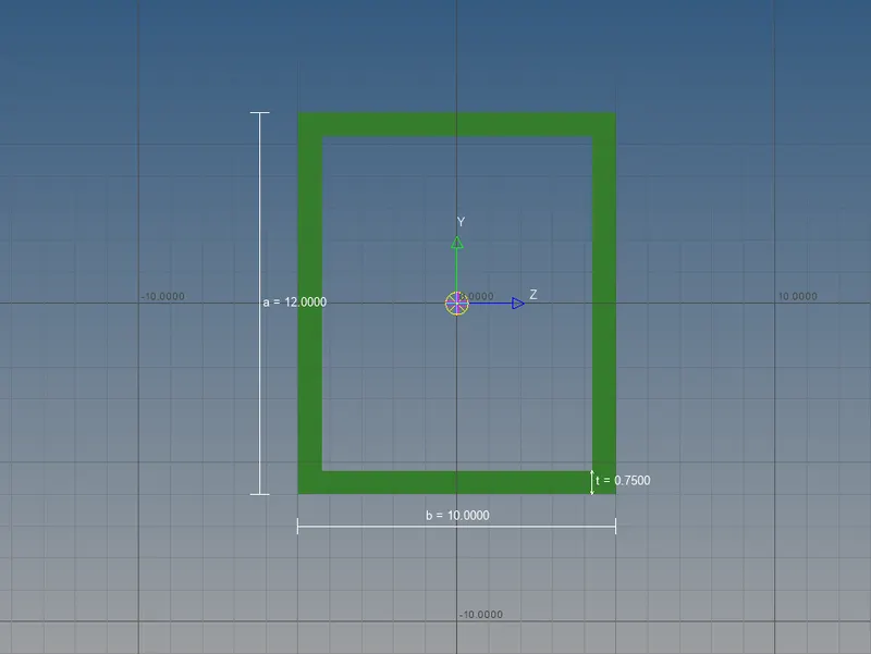
figure - Box section
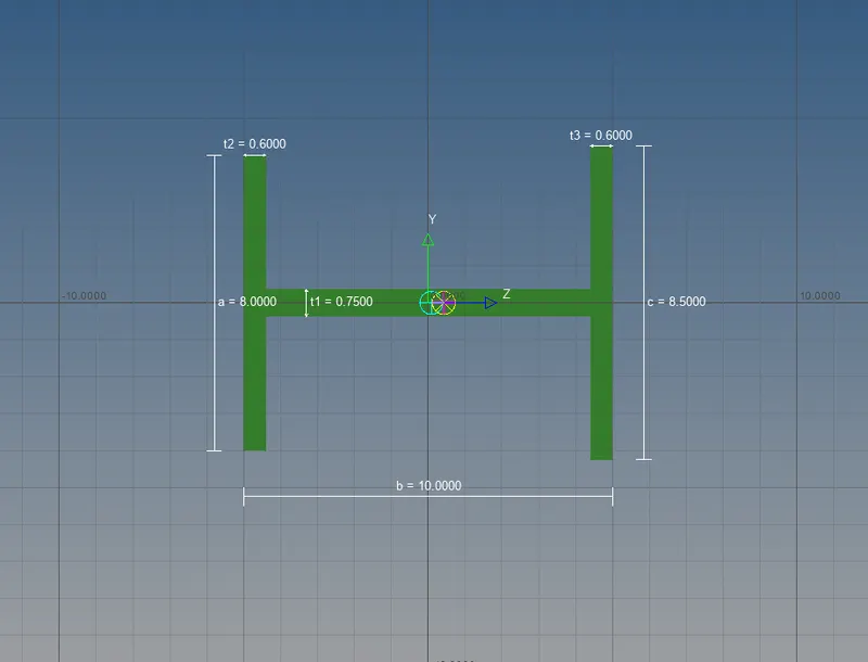
figure - I section

figure - X section
FINAL RESULT:
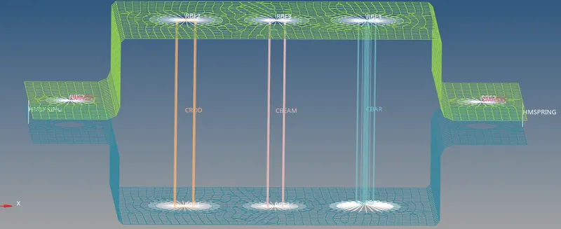
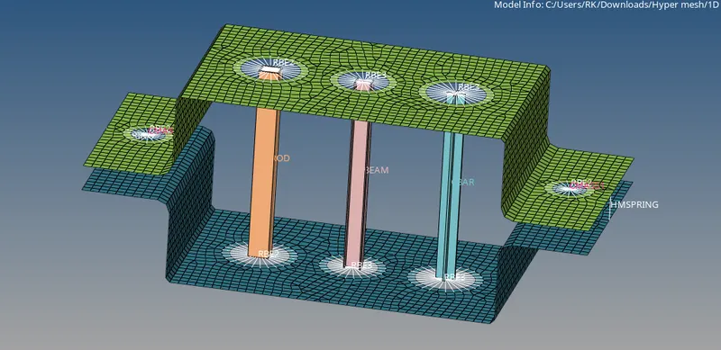
figure - 2D Detailed element representation of all the Cross sections assingned as property