1D Element Creation for Bracket
AIM:
- To generate mid-surface for the given Bracket and to mesh the bracket with element size of 5 units.
- To create 1D bar, Rod and Beam element from the given data.
- To assign thickness, material and property to the components.
OBJECTIVES OF THE PROJECT:
- To generate mid-surface for the bracket component.
- To give washer split for the areas with pin holes.
- To mesh the mid-surface with element size of 5 units.
- To assign RBE2 and RBE3 elements.
- To create 1D Bar, Rod and Beam elements using Hyperbeam.
- To assign material card to the component.
- To sign property and thickness to component.
PROCEDURE:
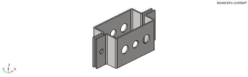
- First step is to import the IGES model. For importing the model, go to FILE > IMPORT > GEOMETRY > FILE TYPE > IGES > OPEN > IMPORT.
- Now, measure the thickness of the component. Go to GEO > MIDSURFACING > REVIEW THICKNESS > SELECT THE COMPONENT.
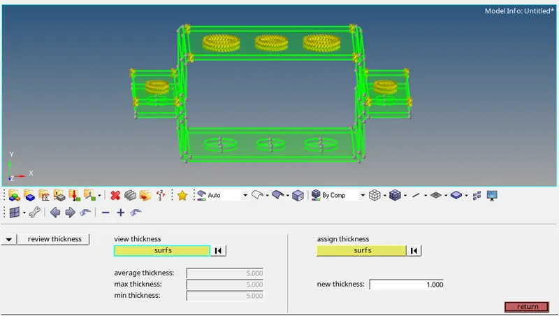
- The thickness for the bracket is found to be uniform.
- Now, to extract the mid-surface for the bracket go to GEO > MIDSURFACING > EXTRACTION OPTIONS > OFFSET+PLANES > AUTO EXTRACTION > AUTO MIDSURFACE > SURFS > SELECT THE COMPONENT > EXTRACT.
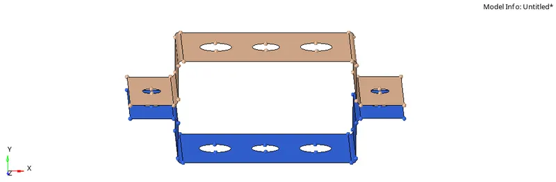
- Offset + Planes option in the extraction options will create joined surfaces instead of creating a single mid-surface. This option is better to distinguish the fillet surfs from the flat surfs.
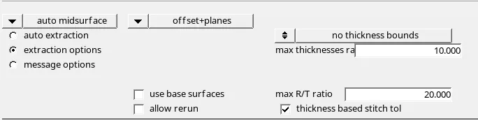
- Now go to COMPONENTS > RIGHT CLICK ON MIDSURFACE_1 > RENAME AS BRACKET_1.
- RIGHT CLICK ON COMPONENTS > CREATE > RENAME AS BRACKET_2.This step is important before extracting the mid-surface for the lower bracket as if not performed will assign mid-surface of both the brackets in a single mid-surface component.
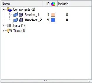
- Similarly, extract mid-surface for the lower bracket.
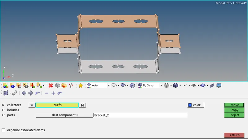
- Now, go to TOOL > ORGANIZE > SURFS > MIDSURFACE_2 > DEST COMP > BRACKET_2 > MOVE. This option will assign the midsurface_2 component to the Bracket_2 component.
- Now, go to DELETE > SOLIDS > ALL > DELETE ENTITIES. This option will delete the solids in the geometry.
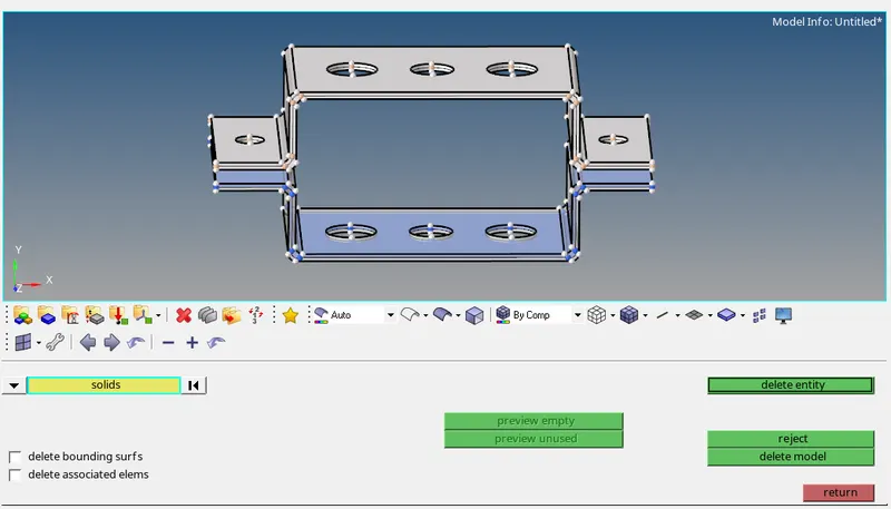
- Also delete the components other than Bracket_1 and Bracket_2.
- Now, go to VISUALIZATIONS > MIXED. This will show the edges according to the color code for free edge, shared edge and T section.
- Now, go to GEO > QUICK EDIT > WASHER SPLIT > OFFSET VALUES = 5 > SELECT THE CIRCLES. This option will create a trim circle or a washer element around the holes for reducing the stress concentration.
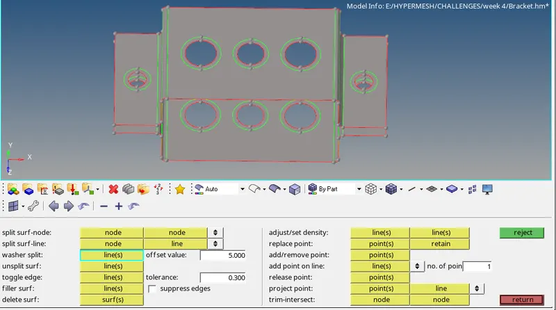
- CREATE > MATERIAL > RENAME AS STEEL > ASSIGN CARD IMAGE AS MAT1.
- This option will create material property and assign steel property values to it.
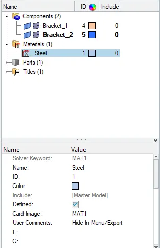
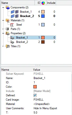
- CREATE > PROPERTY > BRACKET_1 > CARD IMAGE > PSHELL > THICKNESS = 5 > MATERIAL > STEEL.
- This will create a property for Bracket_1 and assign steel material and thickness to the property.
- COMPONENTS > BRACKET_1 > PROPERTY > BRACKET_1.
- This will assign the bracket_1 property and material to the Bracket_1 component.
- Similarly, create Bracket_2 property and assign it to the Bracket_2 component.
- Now, for meshing the bracket go to 2D > AUTOMESH > SURFS > ALL > ELEMENT SIZE = 5 > MESH TYPE MIXED > MESH.
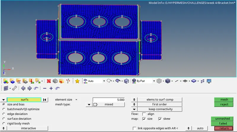
- Now, for the washer elements checks for the same no of nodes at the inner and outer edge. To increase the no of nodes left click on the no displayed, to reduce the no of nodes right click on the no displayed.
- Note that the no of nodes at the inner and outer edge of the washer split elements should be same to reduce disorientation and create only quad elements.
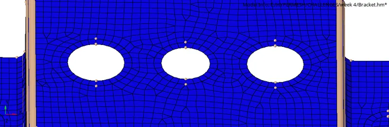
- After the mesh is completed CREATE > COMPONENT > RENAME AS LINKS.
- Now, make links as the current component and start creating RBE2 and RBE3 elements.
- Go to 1D > RIGIDS > CREATE > MULTIPLE NODES > CALCULATE NODES > NODES BY PATH > SELECT THE NODES AT THE HOLE REGION > TRANSITIONAL DOF CONSTRAINED > CREATE.
- This will create RBE2 cluster element. Create RBE2 element at the hole provided in the drawing.
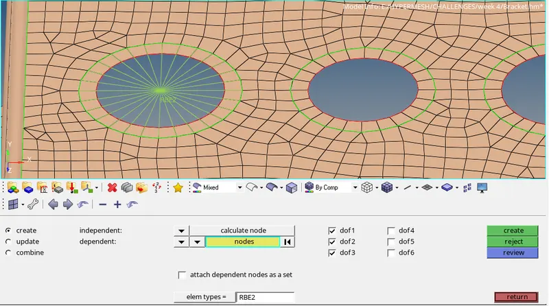
- Now, similarly create RBE2 element at the Braket_2.
- Now, to create RBE3 element go to 1D > RBE3 > CREATE > NODES BY PATH > SELECT THE NODES > CONSTRAINT DOF > CREATE.
- This will create RBE3 elements and constraint the DOF according to the given data.
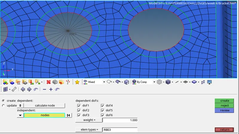
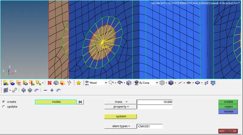
- Now, to assign mass at the desired location go to 1D > MASSES > CREATE > MAGNITUDE = 10 > ELEMENT TYPE > CMASS1 > SELECT THE NODES > CREATE.
- This will assign mass of 10 magnitude at the nodes selected.
- Now, to deploy spring connection go to 1D > SPRINGS > CREATE > SELECT NODE 1 AND 2 > ELEMENT TYPE > CELAS1 > CREATE.
- For spring elements select DOF2 (in Y Direction) as the constraint.
- The spring element is represented by celas1.
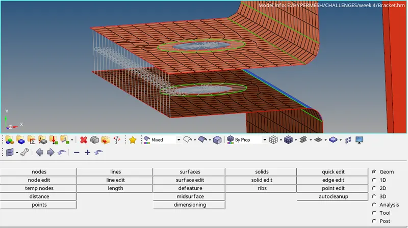
- Now, to create Bar, Rod and Beam elements, first create individual property card for each element.
- Then, go to HYPERBEAM > STANDARD SECTION > SECTION LIBRARY: HYPERBEAM > SECTION TYPE: THINWALLED BOX > CREATE.
- This option will open a new window called Hyperbeam which is basically used for providing cross section area values for the bar, rod and beam elements.
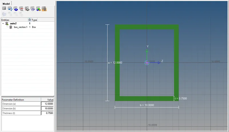
- Rename the section as ROD and assign the dimension values as provided.
- In the same Hyperbeam window RIGHT CLICK ON AUTO > CREATE > STANDARD SECTION > HYPERMESH > I SECTION.
- This will create I section beam element area. Assign the dimension values as provided.
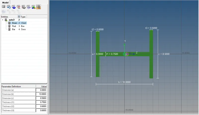
- CREATE > STANDARD SECTION > OPTISTRUCT > CROSS. This will create X bar element section. Assign the dimension values as provided.
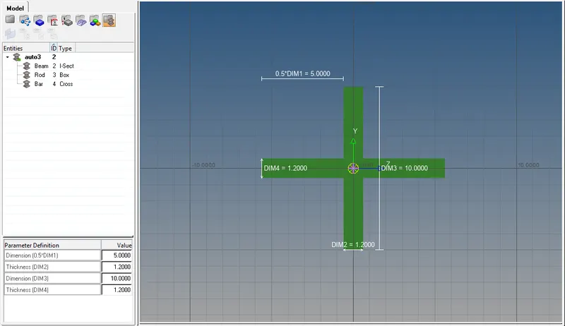
- Now, switch back to the Hypermesh window.
- Go to 1D > BARS > SELECT NODE A AND NODE B > ORIENTATION > ELEM TYPE > CBAR > CREATE. This will create 1D bar element.
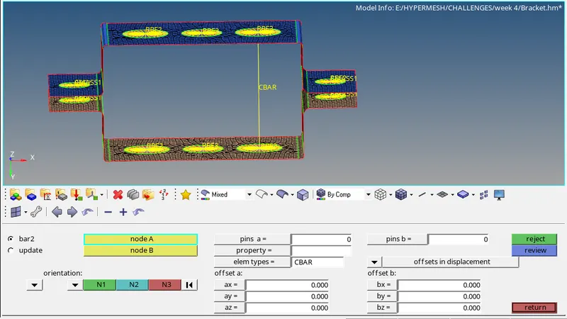
- Similarly, to create beam element go to 1D > BARS > SELECT NODE A AND NODE B > ORIENTATION > ELEM TYPE > CBEAM > CREATE.
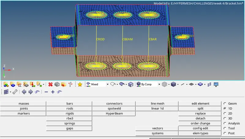
- For rod element go to 1D > RODS > CREATE > SELECT NODE A AND B > ELEM TYPES > CROD > CREATE.
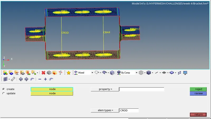
- The bar, rod and beam element in the graphics area is shown by a link.
- Now, we have created property ID for each Bar, Rod and Beam element.
- We have to assign CARD IMAGE as PBAR, PROD and PBEAM for Bar, Rod and Beam property card respectively.
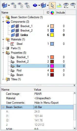
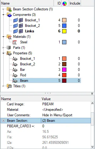
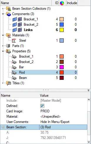
- Now, go to 1D > BARS > UPDATE > PROPERTY > BAR > ELEM TYPE > CBAR > SELECT THE ELEMENT > PROPERTY TYPE > UPDATE. This will update the bar property to the cbar link.
- Similarly, for beam element 1D > BARS > UPDATE > PROPERTY > BEAM > ELEM TYPE > CBEAM > SELECT THE ELEMENT > PROPERTY TYPE > UPDATE.
- For the Rod go to 1D > RODS > UPDATE > PROPERTY > ROD > ELEM TYPE > CROD > UPDATE.
- Now, to check whether the property are assigned to the links or not, go to VISUALIZATIONS > 1D DETAILED ELEMENT REPRESENTATION.
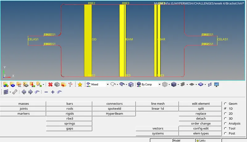
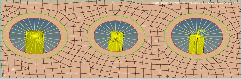
- This option will convert the 1D element into the assigned cross section area and solid representation.
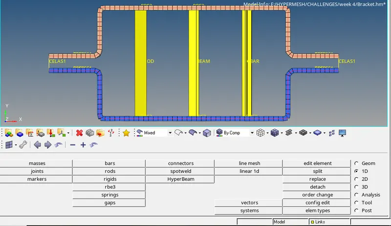
- Similarly, for assigning thickness to the component go to VISUALIZATIONS > 2D DETAILED ELEMENT REPRESENTATION.
- This option will represent the 2D shell elements to the assigned thickness.
- Now, go to FILE > SAVE MODEL.
LEARNING OUTCOMES:
- To extract mid-surface.
- To deploy washer elements.
- To deploy mesh on the component.
- To deploy 1D elements such as bars, rods, beams masses and spring elements.
- To assign cross section dimensions to the 1D elements using Hyperbeam.
- To assign Material ID and Property ID to the components.
CONCLUSION:
- Hence by performing this project we understood the use of GEOMETRIC and 1D tool menu to mesh and deploy connections to the component.