Week 4-1D Element Creation Challenge
CHALLENGE -3 : 1D Element Creation Challenge
AIM:
- To Mesh the given component with the element size of 5 Units.
- To create 1D elements on the component with the given cross-section and DOF.
OBJECTIVE:
- Understanding the use of 1D elements.
- Deploying the suitable 1D elements on the respective places.
- Assigning the cross-section and property.
GIVEN CRITERIA
a. Rod element:- Translational DOF should be Constrained with RBE2 link
Cross-Section: BOX- Dimension a= 12 mm
dimension b=10 mm
Thickness t= 0.75 mm
b. Beam element:- All DOF should be constrained with RBE3 link
Cross-Section: I Section- Dimension a= 8 mm
Dimension b= 10 mm
Dimension c= 8.5 mm
Thickness t1= 0.75 mm
Thickness t2= 0.6 mm
Thickness t3= 0.6 mm
c. Bar element:- Constrain only x and y DOFs With RBE3 link
Cross-section: X section- Dimension DIM1= 5 mm
Thickness DIM2= 1.2 mm
Dimension DIM3= 10 mm
Thickness DIM4= 1.2mm
d. & e. Apply the mass of magnitude 10 with the RBE2 link
f. Join the two components with Spring elements.
THEORY:
- Midsurfacing: The surface between two surface is midsurface. For a 3D component we have to produce a 3D mesh (hexa or tetra). Also the number of nodes and number of elements increases for 3D mesh, which in turn increases the storage space required to store the entire component as well as the processing time needed to analize the entire component.
To avoid all these, midsurface is created, where we can represent the entire 3D model by the midsurface and create a shell element in them. Shell elements are the 2D representation of the 3D elements (hexa & tetra) - Rigid/RBE2 Elements: These are basically elements, which have infinite stiffness. (i.e. These elements will never bend and move when load is applied). Load transferred through RBE2 elements will be the same/ constant. RBE2 will distribute the load equally to each element irrespective of their position/distance from the Independent node.
- RBE3 Elements: It can moved up, down, forward and backword as per applied load. In RBE3, Load will not be uniformly distributed. Load distribution will be more for the elements which are near to Independent nodes than the elements which are comparatively far from the Independent nodes.
PROCEDURE:
- Phase -1: Importing Model and Midsurfacing
Model file name: PARALLEL_BRACKET.IGS
- First, Import the model in the hypermesh. Import → Geometry → Give file type as IGES → Import
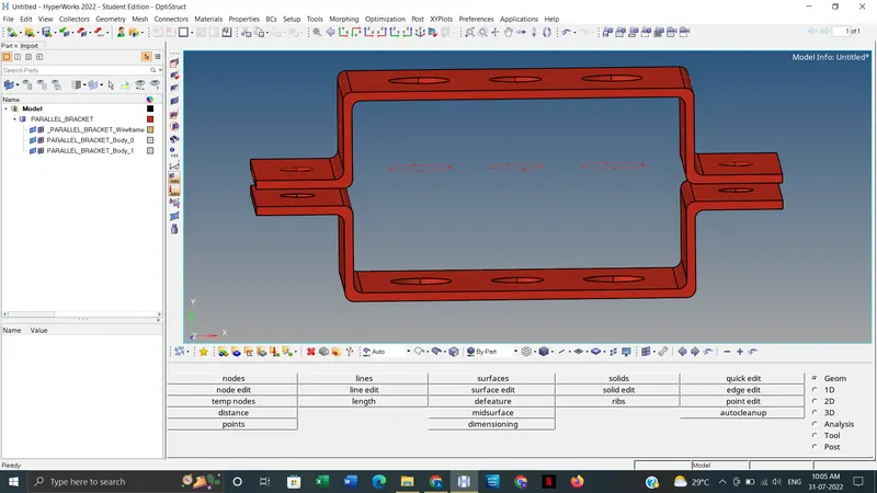
- For making midsurafce, open the midsurface option from the geometry section.
Geom. → midsurface → select one component → extract.
For the surface with uniform thickness the midsurfacing will be proper.
Then hide the solids. Rename the formed midsurface as Bracket_1. Then we want to create midsurface for other component. Before doing that create component tab and rename it as Bracket_2.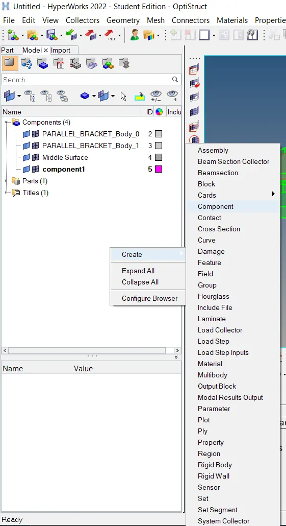
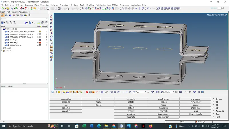
- Then delete all the solids. Then delete the imported component tab named (PARALLEL_BRACKET_Body_0 and PARALLEL_BRACKET_Body_1). Then we will be left with 2 mid surfaces.
- Move the last made midsurface to the Bracket_2.
Tools → Organize → gave dest. component = Bracket_2 & collectors as surface → select the midsurface → Move. Then delete the middle surface tab.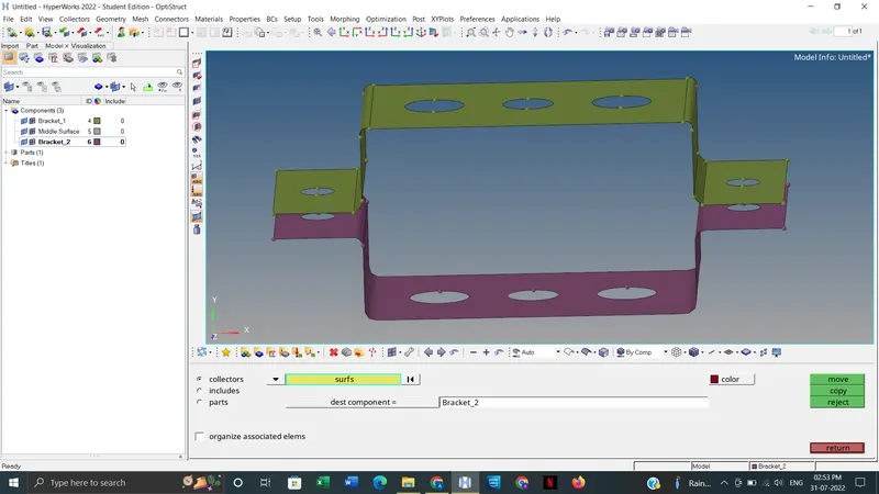
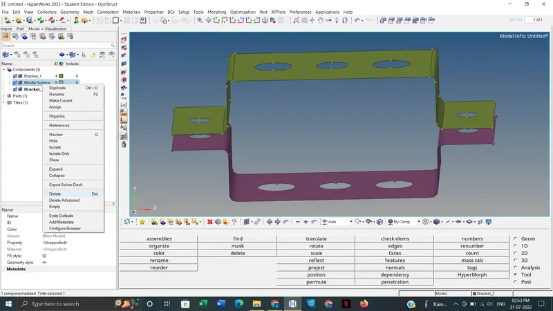
- Phase - 2: Assigning material and property
- After creating midsurface, we need to assign material and property. For assigning material,
Create → material. After pressing return we have to edit. Give name as steel & Card image as MAT-1.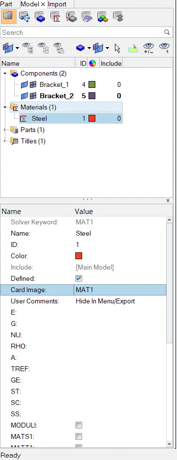
- After that, assign property (Create → property). Name the created 2 property tab as Bracket_1 and Bracket_2. Gave the thickness as needed (Say 5 units) by clicking on the property tab name. Also make sure that Then assign property to the component.
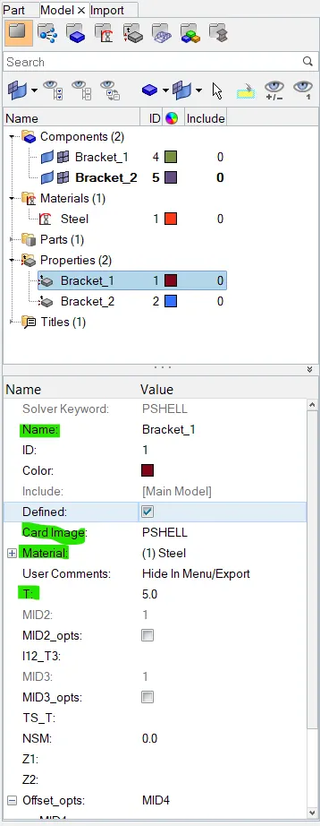
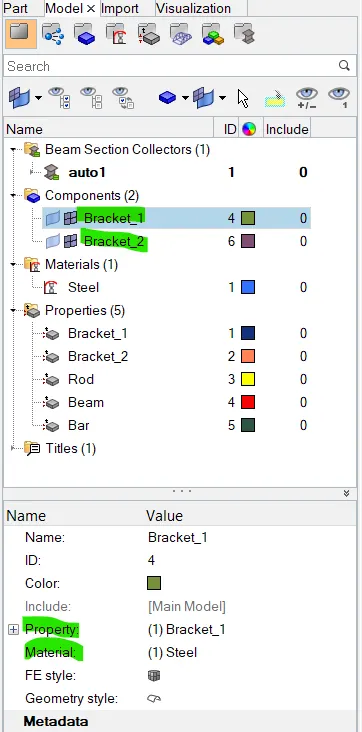
- Phase - 3: Meshing
- Before performing 2D automeshing, gave 5 units offset washer split.
Geom. → quick tool → washer split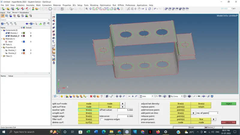
- Then go the 2D automesh, gave mesh type as mixed and element size as 5.
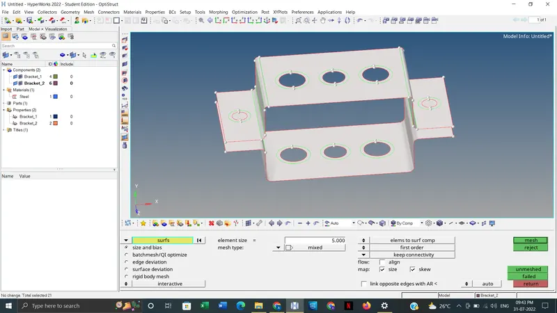
After meshing,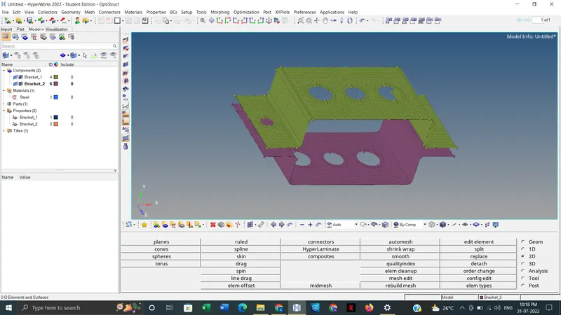
- Phase - 4: Deploying 1D elements and assigning cross-section.
- The first step is to create the RBE2 and RBE3 link at the respective holes as specified location by providing the required DOF (Degree of Freedom).
For RBE2 link,
1D → rigids → create → gave element type as RBE2 and select nodes by path→ create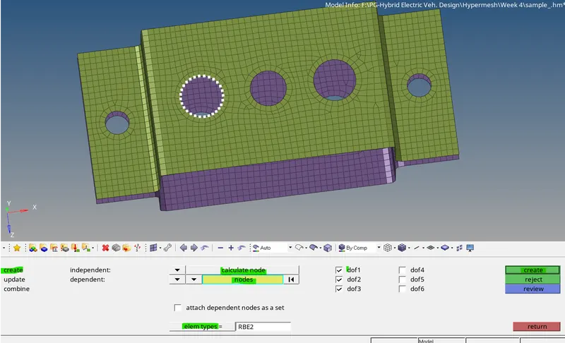
The tick marked DOFs are constrained. Simliarly, we create RBE2 link at specified location (a, d and e) with specified DOFs.
Here dof1, dof2 and dof3 are dof - translation in x, y & z direction respectively. While dof4, dof5 & dof6 are dof - rotational in x, y & z direction respectively. If gave tick mark to any of these, then that particular dof will be constrained.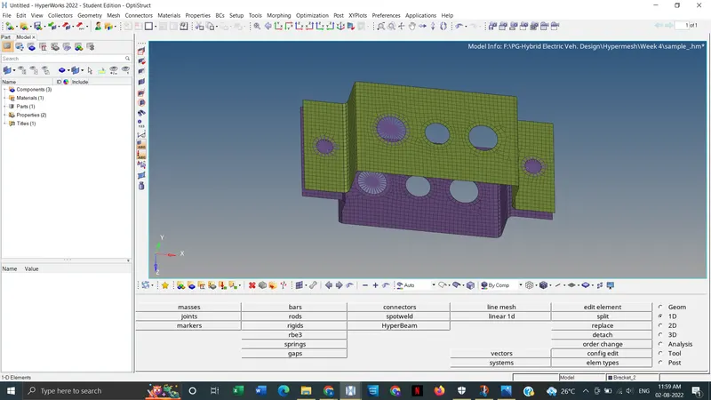
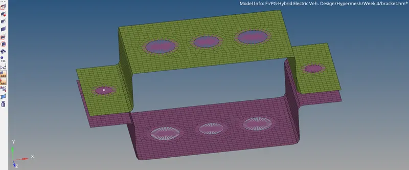
- Then create RBE3 link at b and c with specified DOFs. 1D → rbe3 → selsect nodes by path → create
- The next step is to providing a mass of magnitude 10 at position d & e (Refere given criteria figure).
1D → masses → give magnitude and select node → create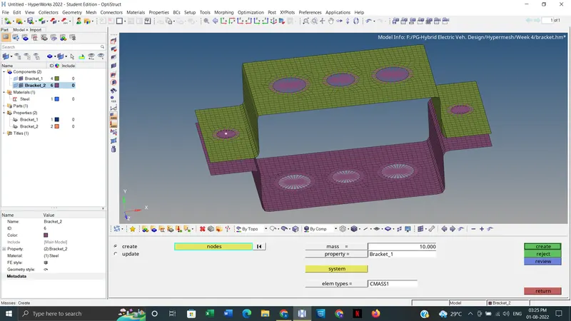
- The next step is to create the rod, bar and beam 1D elements at the respective node points.
For rod, 1D → rods → give element type as CROD and select nodes → create
For beam and bar, 1D → bars → select nodes & orientation and give element type as CBEAM for beam & CBAR for bar → press tab key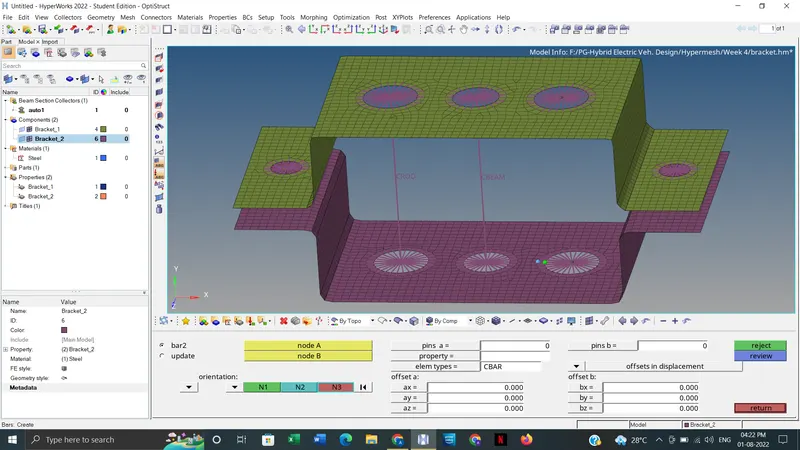
- Then create spring element at specified location to join the two component.
1D → springs → select nodes → create - We need to assign cross-section and property to the 1D bar, beam, rod element.
So, click on 1D → Hyperbeam → standard section → gave standard section library as Hyper Beam and also select the cross-section type we needed (Say thinwalled box for rod element) → Create
After pressing the create, a new window of Hyper Beam opens. Gave the dimension we needed.
For creating next I- cross-section click, left click → create → standard section → Hyper Beam → Standard I section
For X - section : left click → create → standard section → OptiStruct → Cross
Also update the dimension we needed.
After that, click on the model view to go back to the previous view.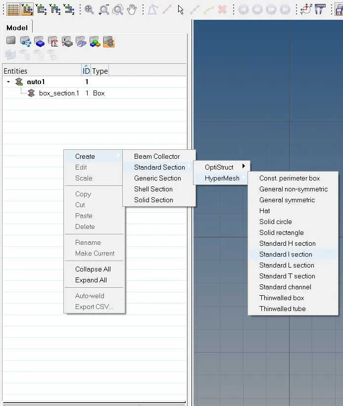
Cross-Section BOX: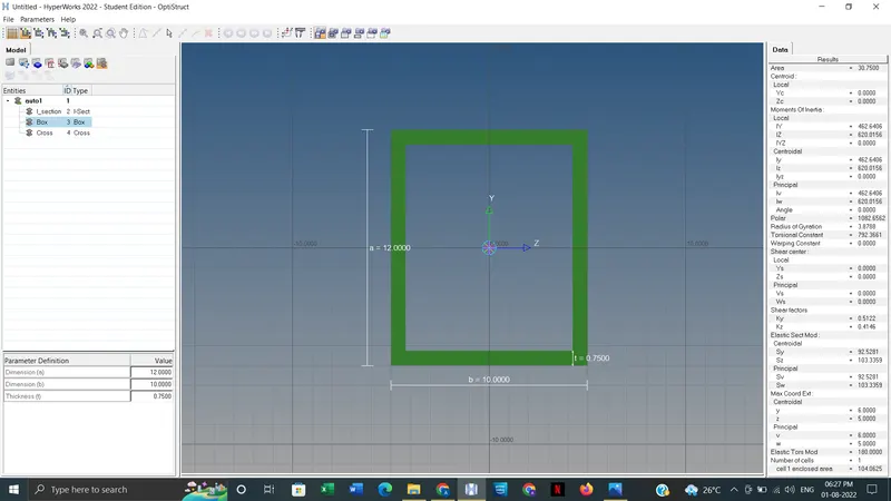
Cross-Section I Section: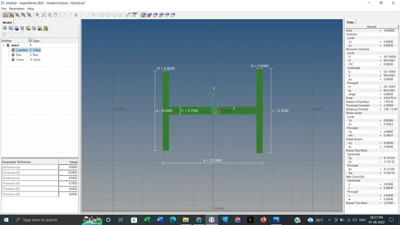
Cross-Section X section: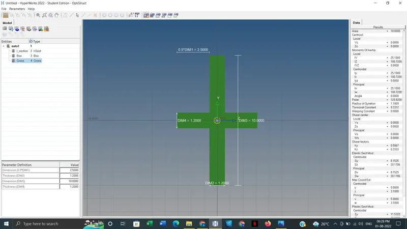
- After going back to Hypermesh view, create property tab for rod, beam and bar element and update the details marked as shown in below figure.
For Rod element: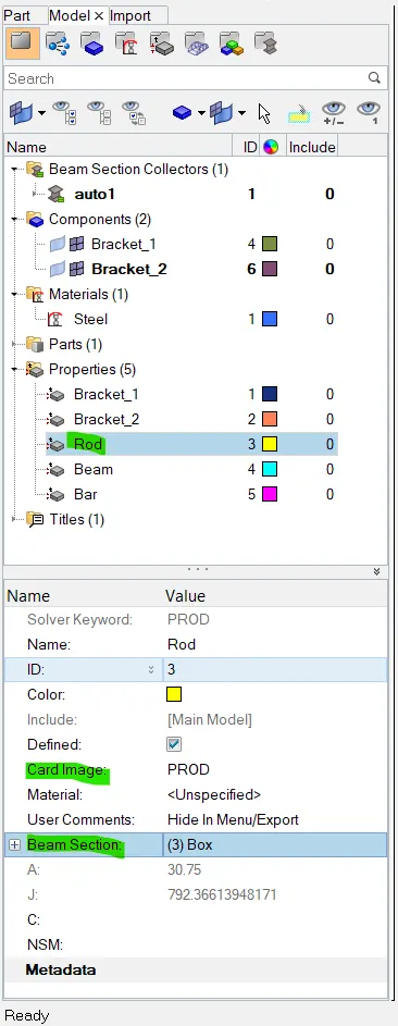
For Beam element: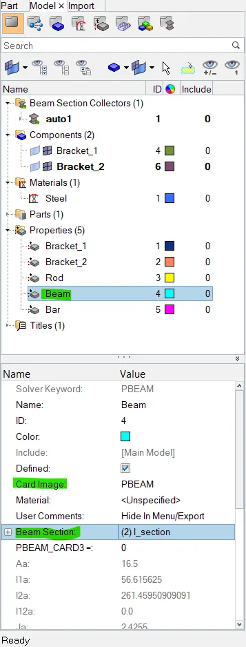
For Bar element: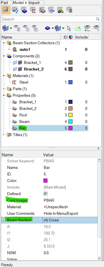
- Then update these property for each element by using update tab.
For Rod, 1D → rods → update → select element and property → update
For Beam & Rod, 1D → bars → update →select element and property → update - To check whether the given details are updated or not, click on, 1D detailed element representaion and 2D detailed element representation.
OUTPUT:
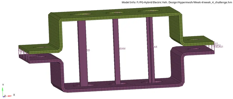
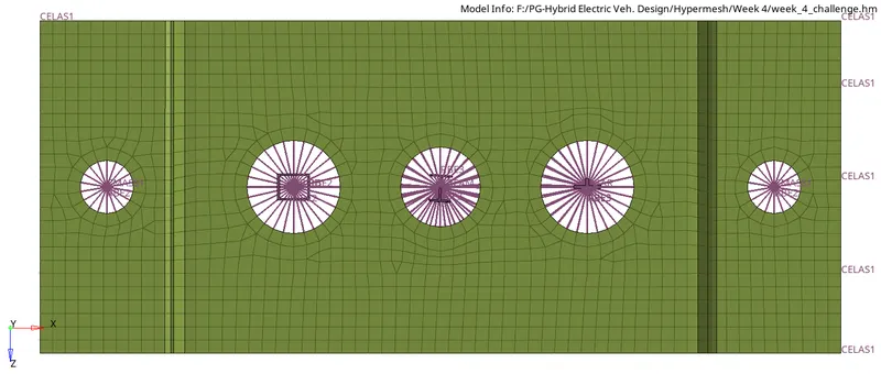
Final Model Image:
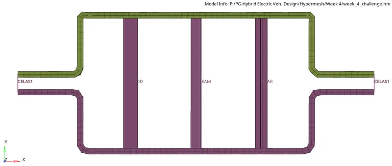
RESULT:
- Meshed the given component with the element size of 5 Units.
- The 1D elements on the component with the given cross-section and DOF are created.
CONCLUSION:
This challenge helps to understand the use of 1D elements and how to deploy suitable 1D elements on respective places. Also helps to get knowledge about assigning property, material and cross-section to the 1D elements. This challenge also explains about the use of midsurfacing feature and how it is usable to represent 3D models.