Week 4-1D Element Creation Challenge
Aim: Mesh the given component and create the 1D elements on the given component of with the given cross-section and DOF
1) Midsurface creation:
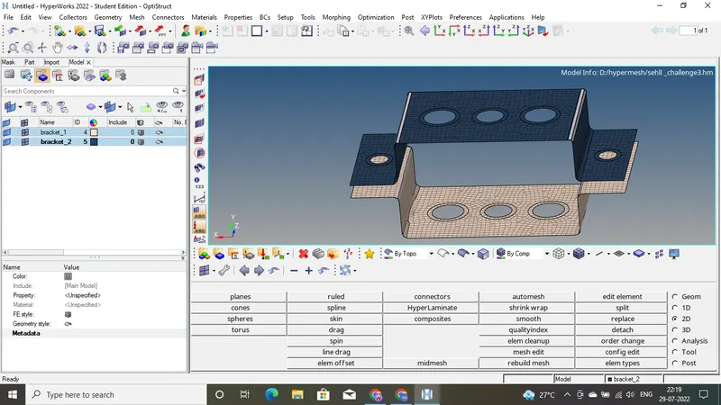
The component we got is a solid shell . Inorder to perform meshing we need to create midsurface for the given solid shell and then perform 2D meshing on this midsurface.Midsurface meshing is opted for components where the geometry thickness is small when compared with the span length of the components.
procedure:
- click on midsurface( geom-> midsurface),select the solid and then press on extract
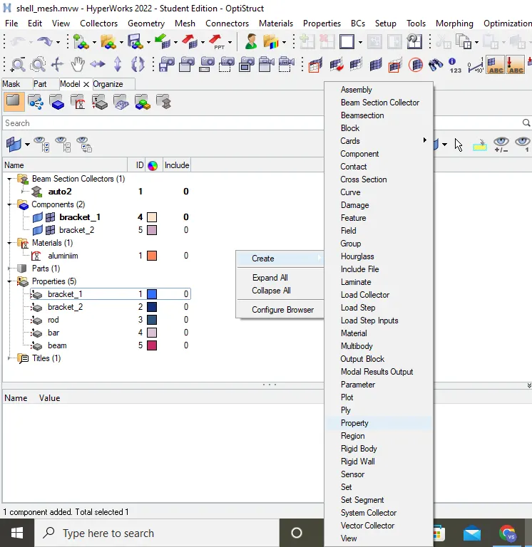
- Assign material to the midsurface. for this ,right click on mode browser -> create -> material. Then select a card image.
- We have 2 mid surface in the same component , so inorder to saperate them . In model browser , two components are created. the go to tool-> organise -> collector , select the element to be moved to a component and select the destination component and click on move.
- to add property to the brackets ,right click on model browser -> create -> property.
- make a material by right clicking in model browser -> create -> material
- click on property we made, select the material we created in material option, select PSHELL for card image. Then right click on the component -> assign -> select the property we made.
- To perform meshing on the midsurface , first the midsurface is checked using autoclean , then washer split(geom-> quick edit-> washer split) is added to holes. Click on automesh in 2D panel and then select the surface to be meshed , change element size to 5 and click on mesh.
- Check the mesh , if the number of holes in inner and outer washer circles of hole are different make it same
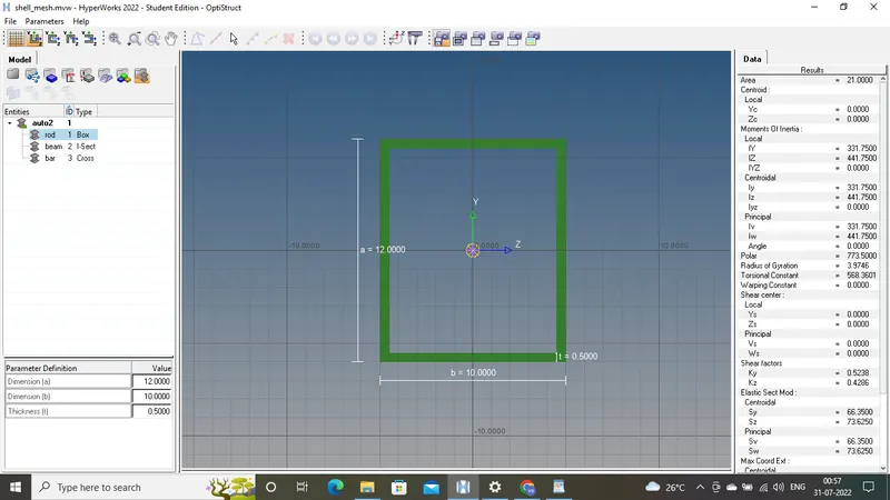
: BOX- Dimension a= 12 mm
dimension b=10 mm
Thickness t= 0.75 mm
1D Element creation:
1) Rod with translational DOF constrained:
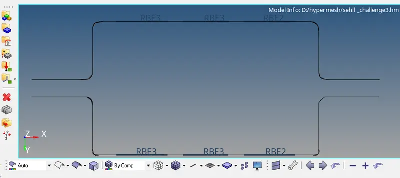
- Open 1D panel , select rigids . In rigids , select element type as RBE2 and then select nodes for the link and then choose the DOF we need , here we need to constrain translational DOF so make sure dof1 , dof 2 and dof 3 is ticked and untic dof4, dof5 and dof 6 then press create
- similarly we make another RBE2 link on the adjacent midsurface
- Click on "Hyperbeam" in 1D panel , this will take to Hyperbeam window , here right click on model browser -> create-> standard section-> hypermesh-> thinwalled box. This will create a thinwalled box we can change dimensions of the rod by clicking on rod , a tab opens below model where we can change dimensions .
- After creating the Box , we go back to hyperworks by clicking on model view.
- open 1D panel , click on rods then select 2 nodes ( the RBE2 link we made before ) , change element type to CROD . rod is made
- Make a new property in model (right click in model browser -> create -> property) for the rod. Change card image of the rod to PROD ,select a material and the select a beam section , Here the beam section is rod we made in hyperbeam.
- Go to "rods" in 1D panel and click on update select property which we made for rod (in our case property is named rod)
- To visualize the rod ,click on "1D detailed element representation".


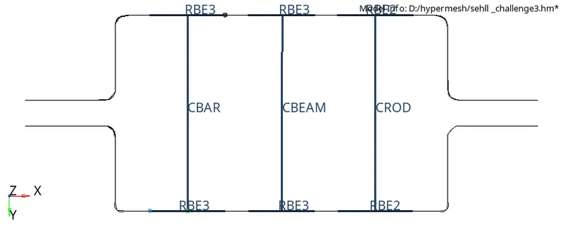
2)Beam with RBE3 links with all DOF constrained:
- Open 1D panel , select "rbe3". In "rbe3",select nodes for the link and then choose the DOF we need , here we need to constrain all DOF so make sure dof1 , dof 2 ,dof 3,dof4, dof5 and dof 6 is ticked .
- similarly we make another RBE3 link on the adjacent midsurface
- Click on "Hyperbeam" in 1D panel , this will take to Hyperbeam window , here right click on model browser -> create-> standard section-> hypermesh-> standard I section. This will create a "I section".Change dimensions to what is given.then go back to hyperworks by clicking on model view.
- Open 1D panel , click on "bars" then select 2 nodes ( the RBE3 link we made before ) , change element type to CBEAM. beam is made
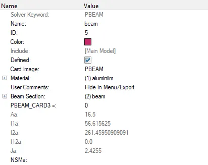
- Make a new property in model (right clicking -> create -> property) for the beam. Change card image of the rod to PBEAM ,select a material and the select a beam section , Here the beam section is beam we made in hyperbeam.
- Go to "bars" in 1D panel and click on update select property which we made for beam (in our case property is named beam)
- To visualize the beam,click on "1D detailed element representation"
Dimensions:
I Section- Dimension a= 8 mm
Dimension b= 10 mm
Dimension c= 8.5 mm
Thickness t1= 0.75 mm
Thickness t2= .6 m
Thickness t3= .6 mm


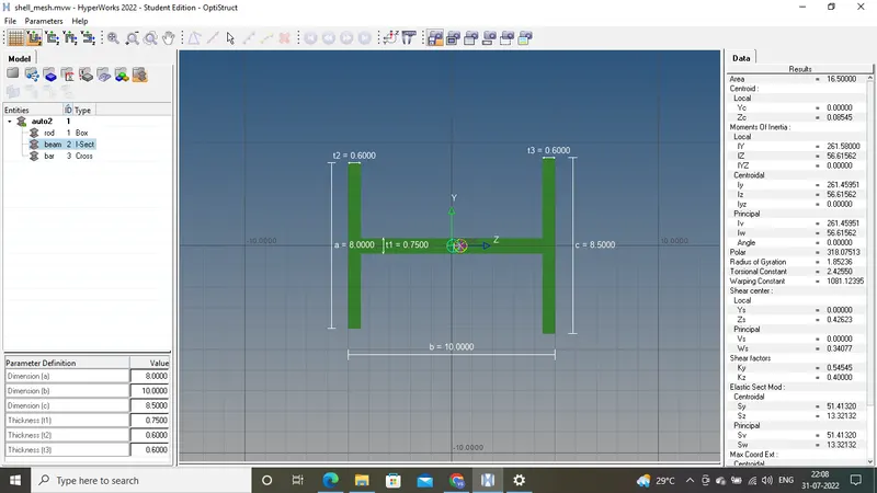
3) Bar element with RBE3 links with x and y DOF constrained :
- Open 1D panel , select "rbe3". In "rbe3",select nodes for the link and then choose the DOF we need , here we need to constrain all DOF so make sure dof1 , dof 2 dof4,and dof5 is ticked .
- similarly we make another RBE3 link on the adjacent midsurface
- Click on "Hyperbeam" in 1D panel , this will take to Hyperbeam window , here right click on model browser -> create-> standard section-> optistruct-> CROSS. This
- will create a "bar of shape X ".Change dimensions to what is given.then go back to hyperworks by clicking on model view.
- open 1D panel , click on "bars" then select 2 nodes ( the RBE3 link we made before ) , change element type to CBAR. beam is made
- Make a new property for the bar. Change card image of the rod to PBAR ,select a material and the select a beam section , Here the beam section is "bar" we made in hyperbeam.
- Go to "bars" in 1D panel and click on update select property which we made for bar
- To visualize the bar,click on "1D detailed element representation"
Dimensions: X section- Dimension DIM1= 5 mm
Thickness DIM2= 1.2 mm
Dimension DIM3= 10 mm
Thickness DIM4= 1.2mm


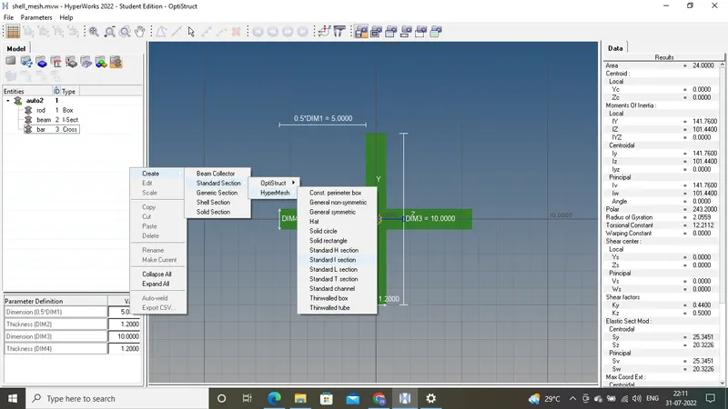

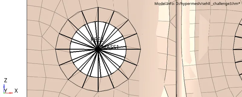
4)Applying mass with RBE2 link:
- First make RBE2 links at holes at both end of the shell using rigids option in 1D panel
- After the RBE2 link is made , click on " masses " in 1D panel
- select the node on which the mass is to be applied (in our case the rbe2 link)
- give the required magnitud and then press on create
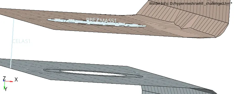
5)Join the two components with springs:
click on springs in 1D panel . select 2 nodes , one on each component
select element type - CELAS1
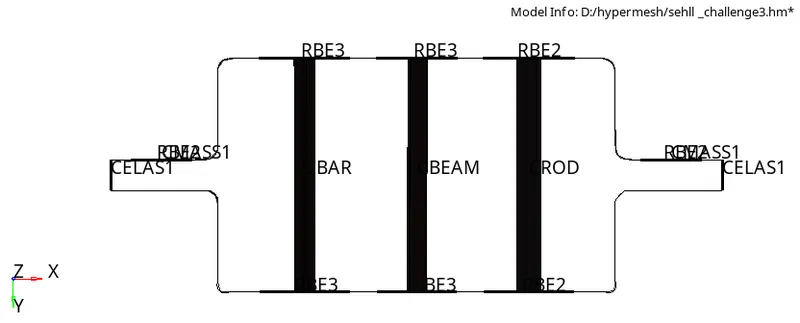
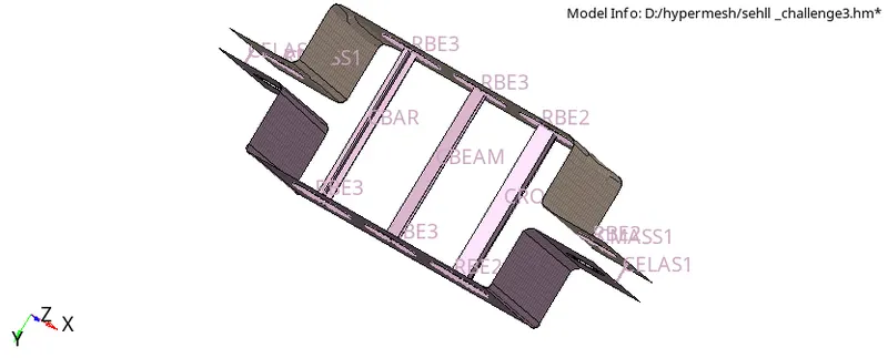
Final image:
conclusion:
The midsurface of the given component is extracted and meshed . the rod , bar, beam and spring connecting two brackets are made and mass is also assigned with arbe2 link