Week 12:Project-1-Meshing of Door Inner Panel Challenge
Project-1-Meshing of Door Inner Panel Challenge
AIM : Extracting Midsurface, 2D Mesh on it and Assigning Thickness
ABSTRACT : Generally car doors mechanisms are typically hinged or attached to the car body. Those doors can be opened either manually or using smart sensor technology. Doors will have a full width panel consisting of arm rest, electric windows, central locking system and speakers. These panels typically consists of a foamed core covered with either textiles or plastics
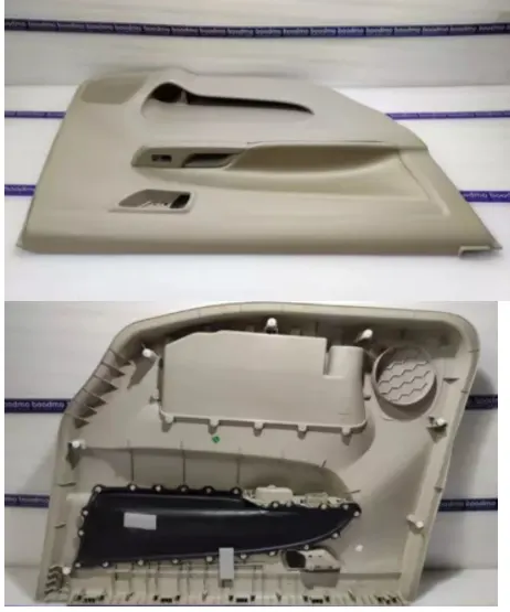
OBJECTIVES : Generating midsurface, geometry cleanup and assigning thickness. Follow the given criteria for 2D meshing.
Target Element Length = 4 Units
|
S.N |
Quality Criteria |
Value |
|
1 |
Aspect Ratio |
5 |
|
2 |
Skewness |
45 |
|
3 |
Warping |
15 |
|
4 |
Taper |
0.5 |
|
5 |
Min. Length |
2 Units |
|
6 |
Max. Length |
6 Units |
|
7 |
Min angle Quad |
45 |
|
8 |
Max angle Quad |
135 |
|
9 |
Min angle Tria |
20 |
|
10 |
Max angle Tria |
120 |
|
10 |
Tria % |
10 |
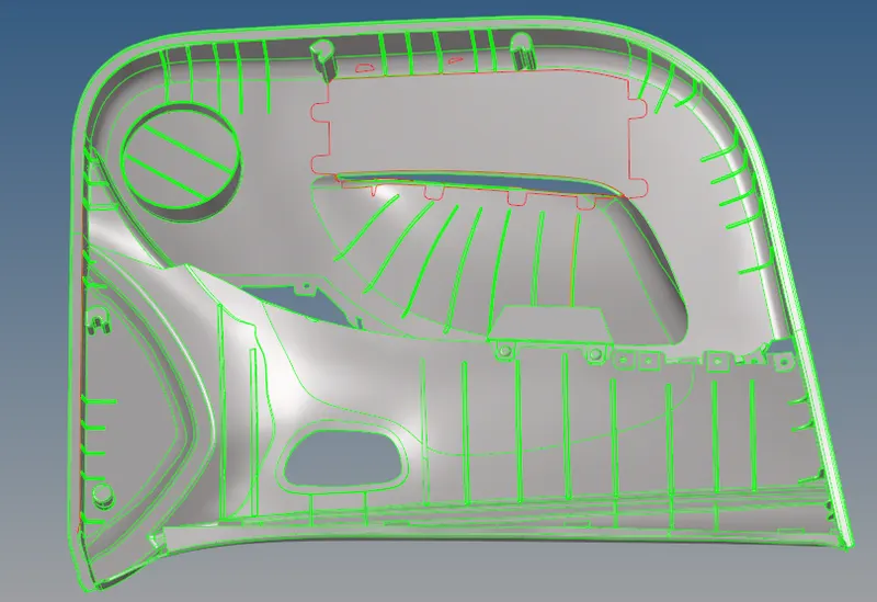
PROCEDURE :
* As we can observe that it is a big component, it will be difficult to extract the mid surface at once, here we can split it into parts as per our convenience.
STEP 1 : To keep the given (Parent) surface safe, we can duplicate and can move it to another collector.
STEP 2 : Organise the 2nd component and splitted parts into other collectors to move them.
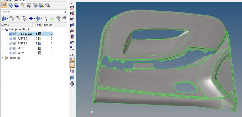
* As I splitted the whole into 2 parts and each midsurface for each part. As the main component contains many geometry cleanup, we have to focus on the accurate manual mid surface extraction.
*Tool--Organise--surface--make new collector current--select dest component--Duplicate--Move
STEP 3 : Delete if any solids any present. We have to measure the thickness of different areas of the surface to offset them, to create midsurface.
STEP 4 : Midsurface extraction (part 1)
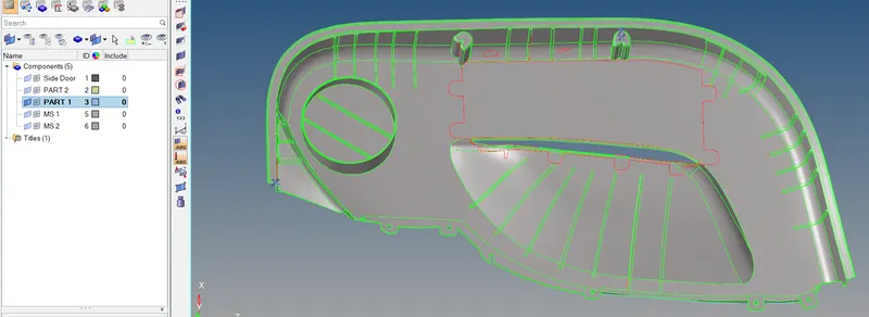
- Here, we can't go for auto mid surface extraction, because we can see there are many attached ribs and other surfaces. In auto it will fail to extract as per our requirements.
- So we have to extract it manually, also creating 2 Midsurface collectors for each to keep the mesh.
- At large areas we can select the whole face and we can offset it using (thickness)T/2, i started with beneath the surface, because it has minimum geometric errors. To offset this we have measured the distance two points F4.
*Geometry--Surface edit--offset--select surface(Duplicate it)--enter value(Check vector normal)--offset.
-After extraction we have to check for the surface for geometry cleanup. dents, overlaps and some glitches may take place,we have to clear them.
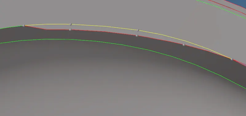
- In above image we can as it failed to capture the surface properly, we can use Quick edit F11 panel for many corrections
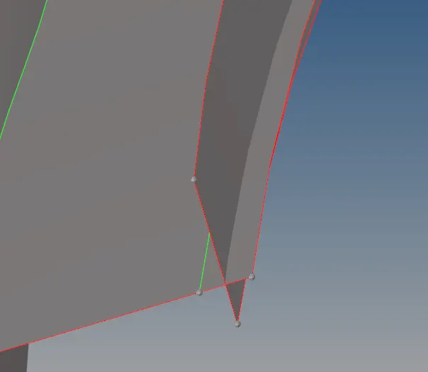
- In the above image, when two surfaces intersect then there must be a green line, for 3 & many surfaces Yellow line, so we have to make sure there is a proper surface connectivity.
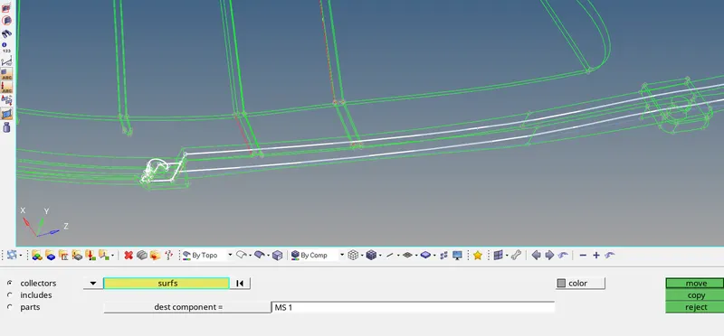
- while offset we have to make the other collector current, then the surface extracted will be placed directly there, or else we can organize it.
*Tool--Organize--collector--select surface--select dest component--move.
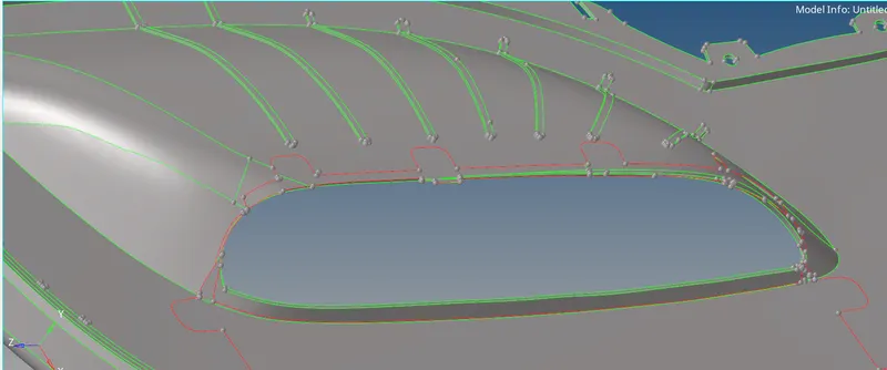
- As we can see there are many ribs, initially we have to defeature them, and we can extract the midsurface.
- To offset we have measure the distance two points F4.
*Geometry--Surface edit--offset--select surface(Duplicate it)--enter value(Check vector normal)--offset
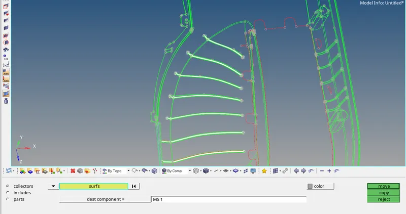
-While offset we have to make the other collector current, then the surface extracted will be placed directly there, or else we can organize it.
*Tool--Organize--collector--select surface--select dest component--move
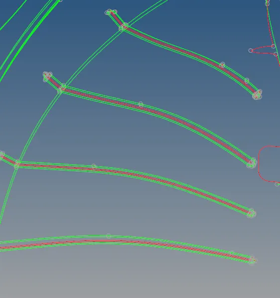
- Midsurface of the ribs
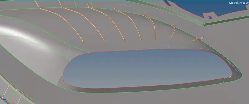
- To the ribs with the below surface, we can use multiple options. Trim both surfaces or extend and many more, when we get to familiar with the commands then we can do it easily. To extend,
*Geometry--surface edit--extend--Select the edges of ribs(extend over edges)--Select the surface (surf: to target--extend)--extend.
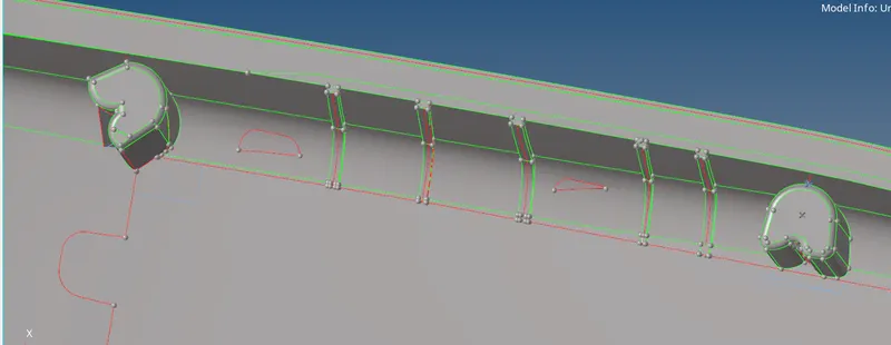
- Similarly we can do for all ribs at different places.
- There exists some mounts, as already mentioned we can represent them into (plus)other shapes. Where it is a tricky process, we have to create a rectangular surface and we can duplicate first and rotate it from the middle then it will be resulted with that formation.
*Tool--rotate--surface--select direction & base--set an angle--rotate+/-
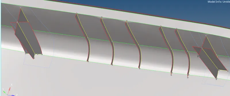
- Above is the result of many steps for ribs and mounts.
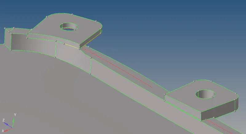
- After extraction of the midsurface, we have to connect both surfaces. The Missing place of those surfaces may occur, so we can translate close to it.
*Tool--Translate--select surface--select direction--set value--Translate +/-
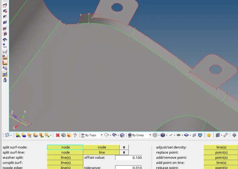
- After that, make that 2 surfaces connected by trim both surf
*Geom--surf edit--trim with surf--(2nd option)select one(Check in both surf trim box)--Select another--Trim
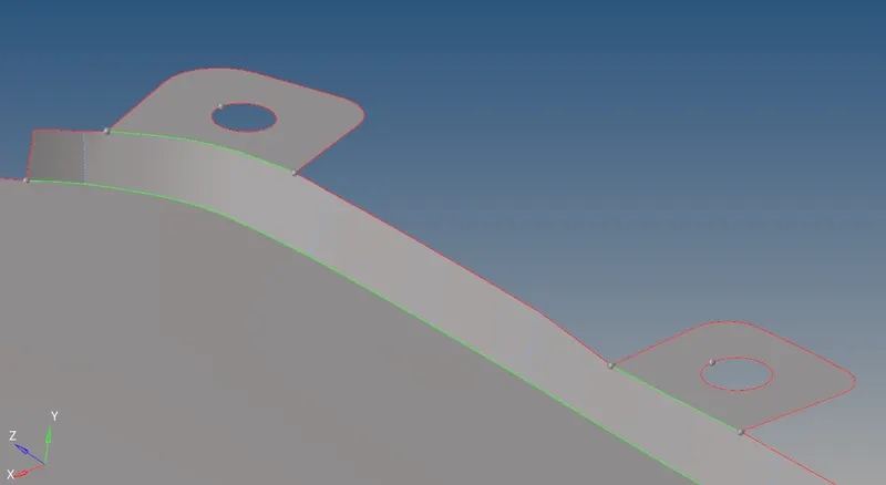
- Do some F11 quick edits to make surf look better.
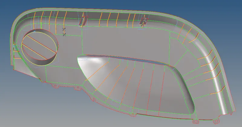
- Examine closely at all surfaces, Ribs and mounts, if any surface got damaged, do corrections, so it will help us in easy meshing.
STEP 5 : Midsurface extraction (Part 2)
- Follow the similar steps as did in part 1.
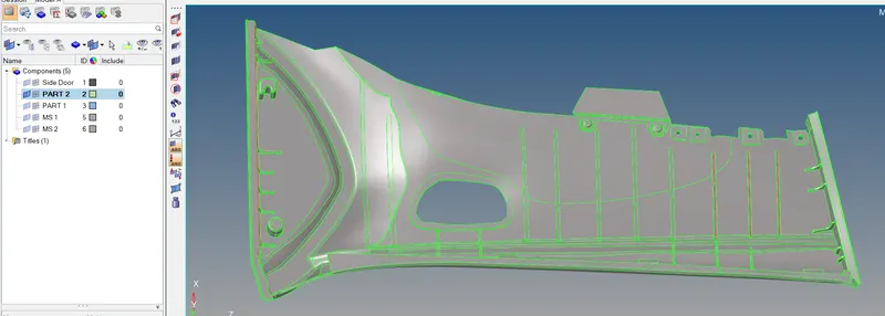
- The below image has some geometrical issue on it so modeling them in the 2D will be difficult.
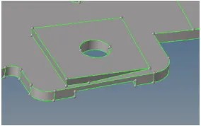
- In those areas, the main objective is to capture the hole so we can take a mid surface by creating a flat surface with a hole like an image below.
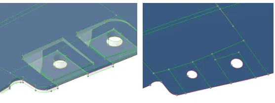
- At Defeatured Ribs we can also extract mid surface using,
*Geom--Midsurace--change to final edit tool--Select one side--another side--extract
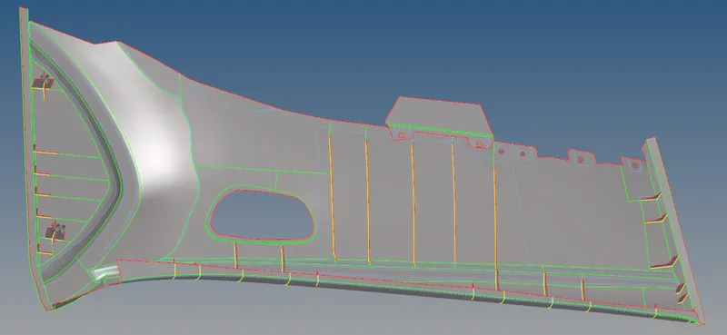
- Examine closely at all surfaces, Ribs and mounts, if any surface got damaged, do corrections, so it will help us in easy meshing.
STEP 6 : Meshing
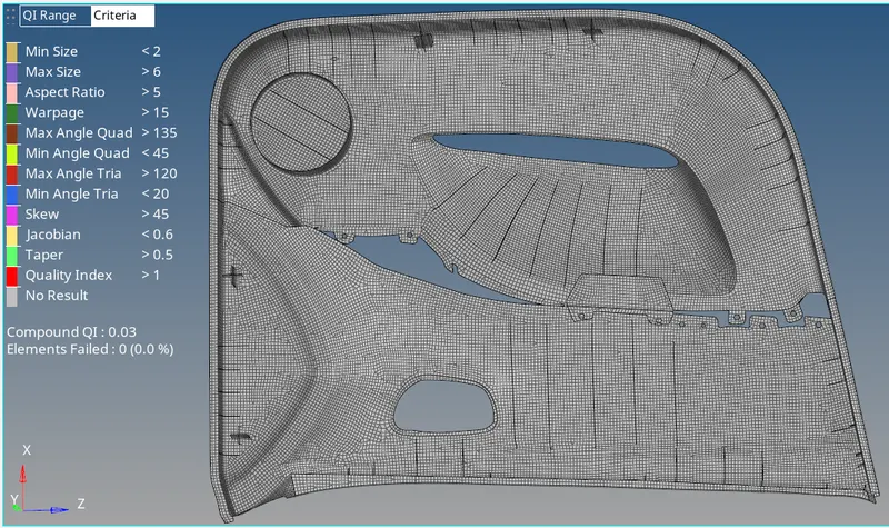
- Before meshing we have to apply the given 2D mesh criteria in Preferences.
- Meshing the whole surface is big task, we have to split the surfaces and have to create fine mesh with minimal errors.
- At holes always try to keep even number of nodes.
- We can toggle some lines as per our convenience, so we can divide large surfaces into small portions, it will help us to keep the mesh proper. - F12 is shortcut for 2D Mesh
- we have to clear the failed elements at each step and also find edges for the mesh.
-In clearing failed elem, there are many tools like F3 for connecting missing nodes, and translating nodes for min size. It is not advisable to go for a Quality index tool for auto correction.
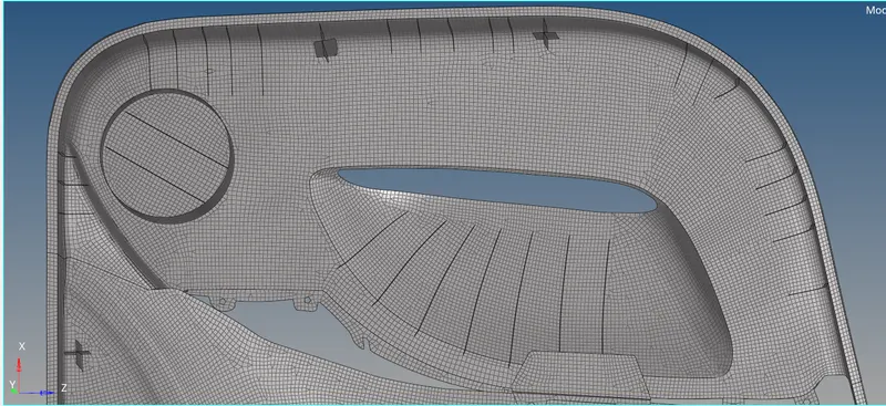
- At ribs we have to maintain only quads, because they are respresntation of stiffness of that part, so we have to remove all trias in those areas.
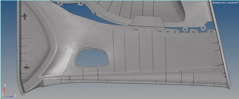
- We have to create a proper mesh, which satisfies all the required criteria.
- For ideal mesh, we have to clear all opposite trias, trias at edges, attached trias, rotational quads, triaquad.
- Attached/Trias at edges can be removed by dragging them away from it, remesh that area.
*2D--quality index--Drag trias.
- Quality index is a handy tool, where many corrections can be done.
- Nodes connectivity is very important, after completion of 2nd surface of that same component, check for edges
*ShiftF3--select area--find edges.
- Many times we miss them, so we won't get proper mesh. We can connect the nodes using-Replace nodes
*F3--select nodes.
- Sometimes we miss the node and feature line connectivity, where this leads the above problem, we can resolve this by projecting those missing nodes to the line
*Tool--Project--To line--nodes (Normal to surface)
- F11 is Shortcut for Quick Edit, a very handy tool, where many helpful options will be available like Toggle, Split surf line-node, replace node/retain.
FINAL VIEW OF MESH :
STEP 7 : Assigning thickness
- There are 2 ways out for it,
1. Manual
- we have to create a property card and we have to measure the thickness of parent geometry and add it in the thickness column, to assign the mesh.
2. Automatic
- We have to keep given parent geom surface ON, click on mesh in the menu bar, Assign--Midmesh thickness
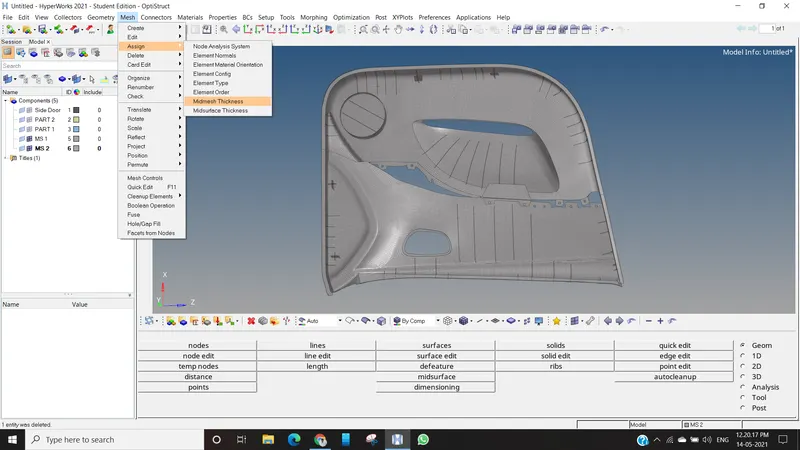
- Another tab from hpyerwork will open
- Select Displayed elements and displayed surface--Calculate thickness 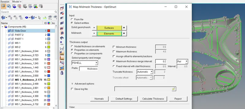
- As we can see apart from main 5 collectors, it created 41 different collectors for assigning thickness to elements, as it consumes much time to give output.
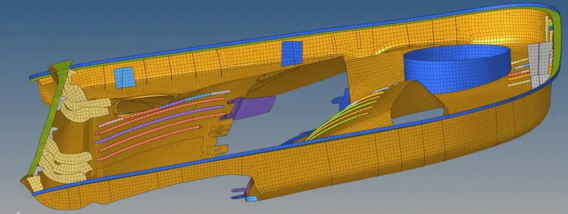
- After completion of that, we can see many elem will be coloured with different colours, in detailed explination, when we compared to parent geom, if any varying thickness is present then we can accept multi colour at that area, or else we have to organize all elem to particular & exact set of Elem group (Colour).
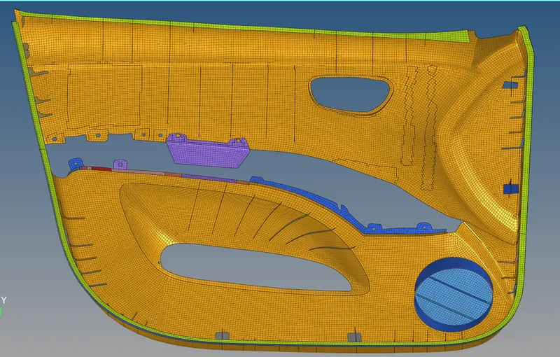
- As we can obsereve the colour difference at some areas, because all parts have different thickness value.
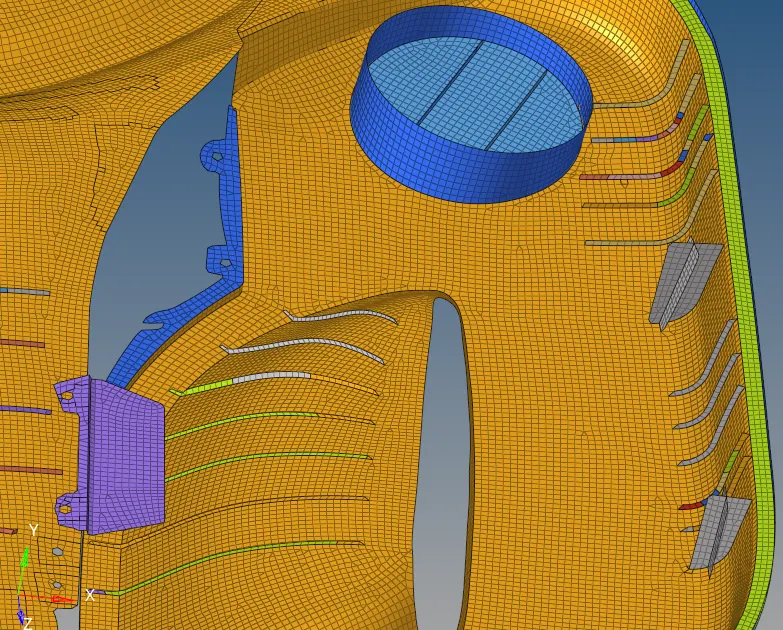
- Many ribs are same, but few have multi colour due to varying thickness.
CONCLUSION :
- Midsurface extraction is most time consuming and prime task in this challenge.
- Prefect midsurface extraction will lead 60% completion of job.
- Geom cleanup will help in fine mesh creation.
- Surface connectivity has to observed carefully.
- Ribs are most important, tricky while extracting and meshing
- Meshing the surface part by part is to be done.
- Removing the failed elements manually, by applying the different tools in that area is important.
- Most of the time ReMesh will correct the surface.
- For ideal mesh, we have to clear all opposite trias, trias at edges, attached trias, rotational quads, triaquad.
- There exist N number of tools to bring Proper mesh, utilize them.
- Quality index tools have to be used very often.
- Connectivity has to be maintained.
- Automatic thickness assigning is a time saver