Week 4-1D Element Creation Challenge
AIM:
To extract mid surface for the given cad model and then assign properties and thickness to it. Then create a 2D mesh with the target element size as '5' and create 1D element on the following component with the given cross section and Degree of Freedom.
OBJECTIVE:
The objective of this challenge is to learn how to extract the mid surface from the solid model and how to create and assign property and thickness to that extracted mid surface. From this challenge we can also understand the hyperbeam option to create 1D elements like bar, rod and beam and how to assign cross section to the 1D element.
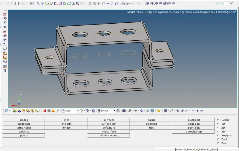
GIVEN CAD MODEL:
PROCEDURE:
- First import the given cad model, for that go to import solver deck> import geometry> file type> IGES > select the required file > click import.
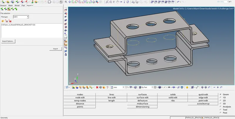
- Now go to model view> to see the components present with that you can view or hide the model by checking on or off. To extract mid surface from the given model go to geometry>mid surface> in the extraction option select skin offset>in the auto extraction option select the surface and give a middle click.
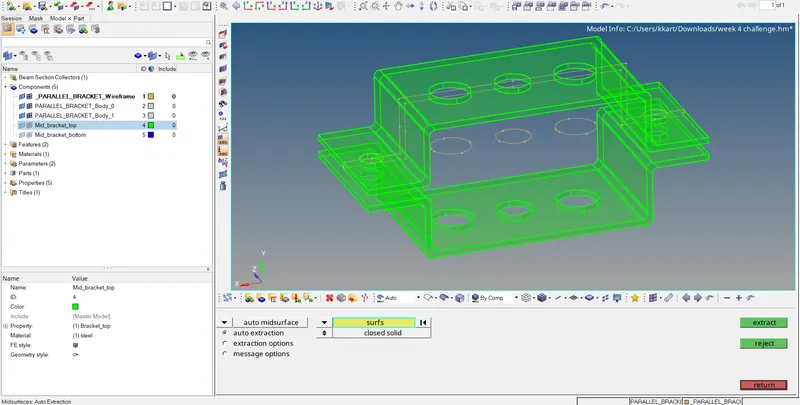
- similarly for the bottom surface of the parallel brackets because if you create the mid suface for bottom surface right after the top surface is created both top and bottom surfaces are considered as a single component so in order to change that first create a component in the model panel and name it as bottom mid surface and then in the extraction option set it as result in the current component and click create.
- For assigning properties for the extracted mid surface, first create material for that right click> create> material>name it as steel>select the required card image>enter the youngs modulus, poissons ratio and density and click create.
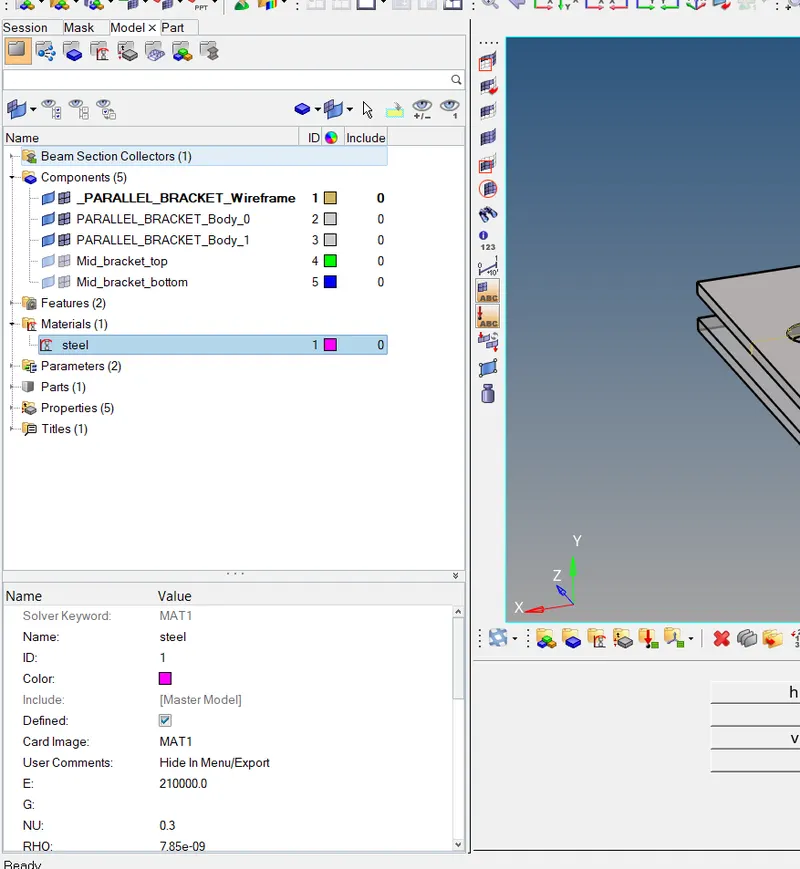
- Once you create a material, right click> create> properties> select PSHELL > select the material as steel that we created above and enter the thickness value and click ok. To find the thickness of the given cad model, go to geometry>dimensioning>select the top and bottom layer of the component and give middle mouse click.
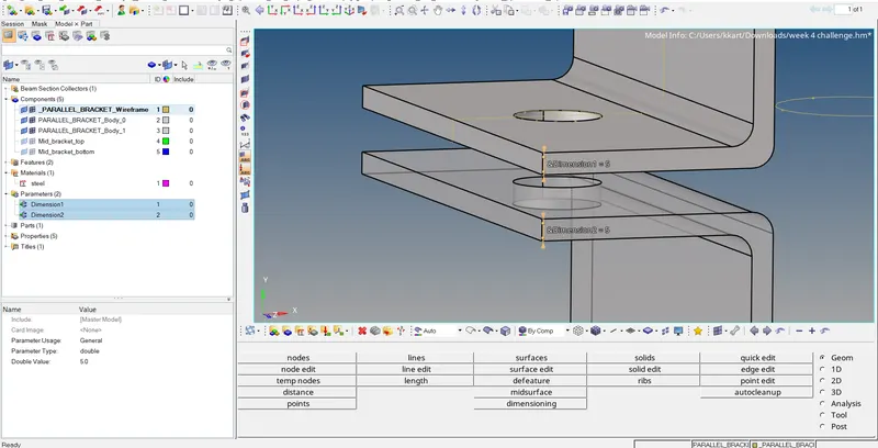
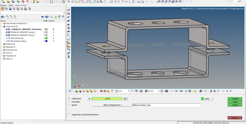
- Once you created the property we have to assign it to the created mid surface but before that we need to move the component from auto created to the one we have created for that go to tools>collectors>surface>select the surface> select the designation component and click move.
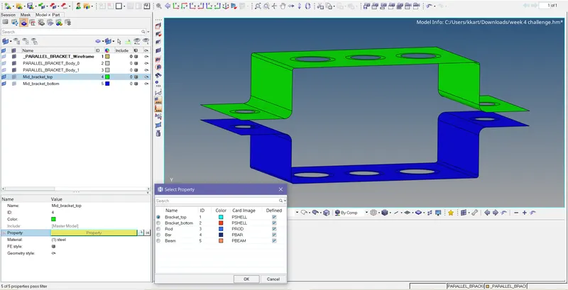
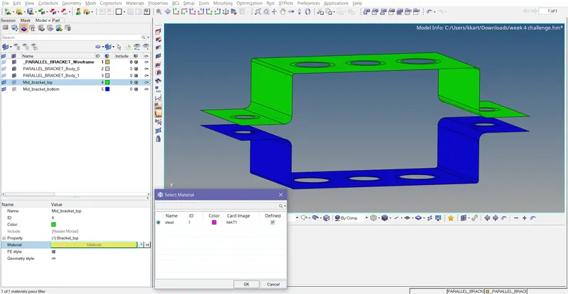
- Now click on the component name and select the required properties and material. Similarly for all the component
- Before we start meshing we have to clear the geometry like we need to create wasser zone over the holes to avoid element collapse. Because the stress acts more on the holes than the surface so mesh flow should be good over the holes that why we are creating a waser split.
- For creating a wasser split go to geometry>quick edit>wasser split>give the zone width(offset value)>select the holes. Once you create wasser split on all the zones click return. The offset value for wasser split should be around target element size if not the element will fail for quality.
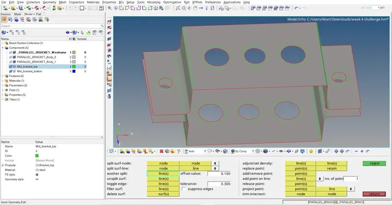
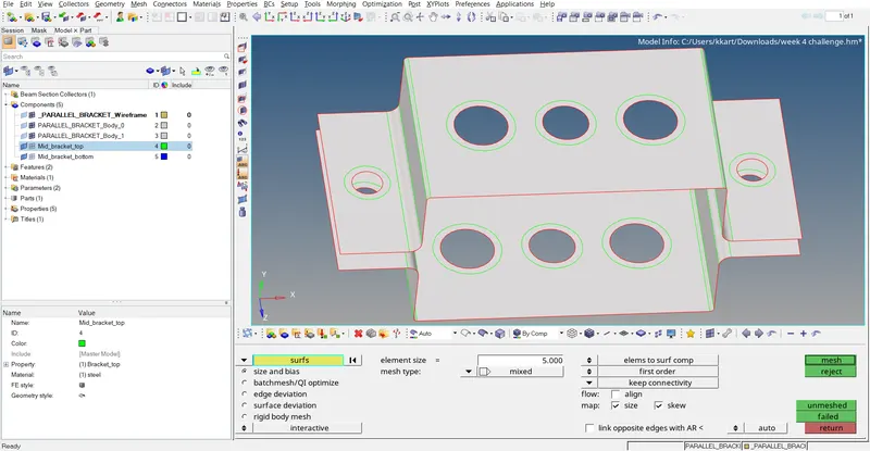
- Now the geometric model is ready for meshing. Now go to 2D>automesh>select surface>displayed>select mixed (mixture of quards and trias elements) select the element size as 5 and click mesh
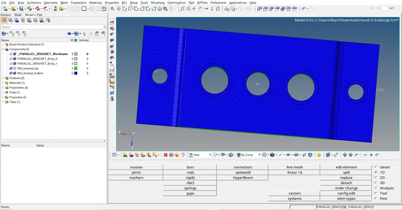
- Thus the 2D mesh is generated with quards and trias now we need to generate the 1D elements like rods, bars and beams and we need to create rigids in the hole as required.
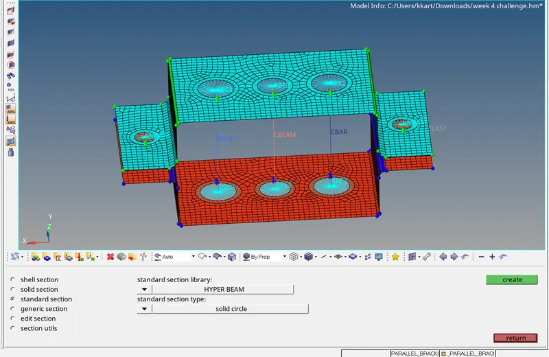
- Before that we need to define the cross section of the beams, bars, and rods for that go to 1D>hyperbeam>select thin walled box>enter the dimensions as given and click create. Similarly for the cross section and L section beams.
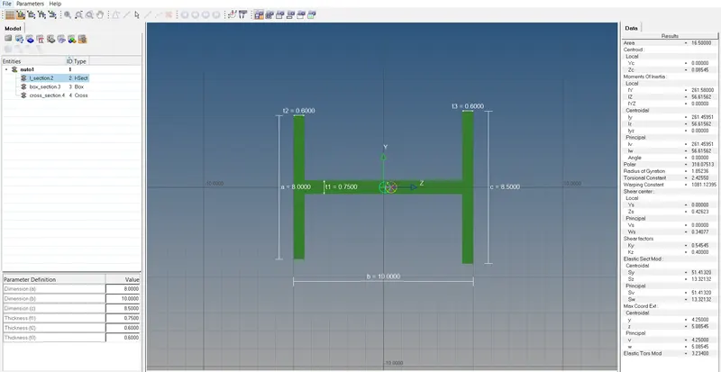
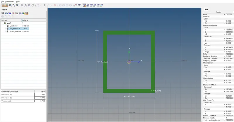
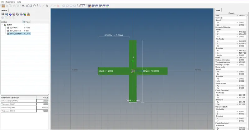
- Now go to 1D, select rigids>create>select the nodes>constrain only transition for that check only (dof1,dof2,dof3) and select the 2 row elements of the hole and click create. The reason for selecting two rows is when we are creating rigids with respect to 1 row of element the stress concentration is more on the 1 row which leads to uncertain results and loading failure in order to avoid that two rows are considered to create rbe elements.
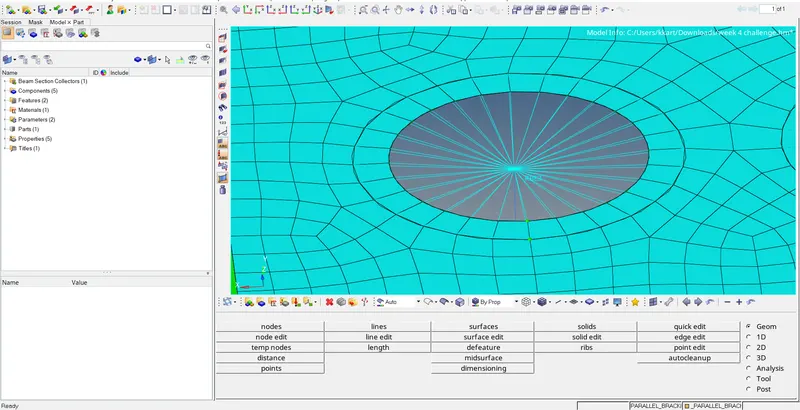
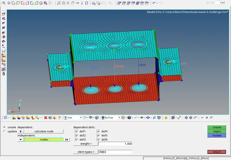
- similarly for rbe3 elements select the two rows of nodes and go to 1D>rbe3>constrain all the degrees of freedom, for that check all the dof boxes and click create.
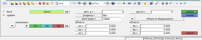
- After creating all the 1D elements now we need to assign the properties, for that go to 1D>Bars>select the 1D element>select the required property>click update>then it asks for which one to update like element type, property etc. we need to select the property and click ok. Similarly for rods and beams update all the required properties.
- Now for creating the spring element go to 1D>spring>select the two nodes between the two parallel surfaces. Constrain translation about x for that check only dof1>select the element type as CELAS and click create.

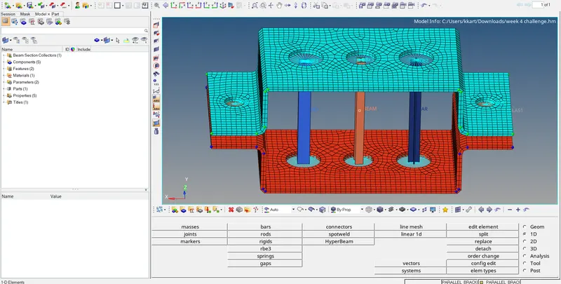
- Now change the view type as 1D detailed representation to see all the cross section that we have applied for 1D elements. and similarty select 2D detailed element representation to see the thickness of the created 2D mesh.
- FINAL COMPLETED MODEL
- RESULT:
- Thus for the given cad model mid surface had been extracted and required 1D element had been created based on the requirement.