Week 4-1D Element Creation Challenge
Answer
- Objective:
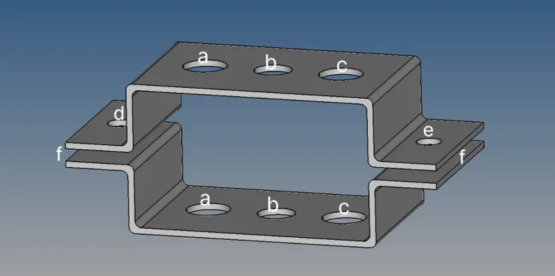
- Creating mesh of the bracket and 1d elements on the following component with given cross-section and DOF of below model.
- Creating mesh of the bracket and 1d elements on the following component with given cross-section and DOF of below model.
- Procedure:
- Importing the geometry-
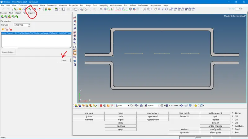
- First of all the model need to import as geometry in hypermesh GUI.
- First of all the model need to import as geometry in hypermesh GUI.
- Confirming the model-
- Checking all the deformities in the model. As we can see the model has many solid fillets. Which is very difficult to mesh.
- Creating mid surfaces-
- The next step is to reduce the solid into mid surface forms because the number of nodes in the case of a solid is exponentially larger than a 2d element. To reduce the following solid into a surface, the mid surface option is used.
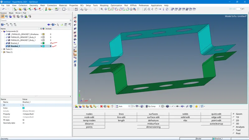
- To create a mid surface we have to consider two solids individually where we create two mid surfaces for each bracket.
- Each mid surface has been saved into two different components.
- Creating washer splits near wholes-
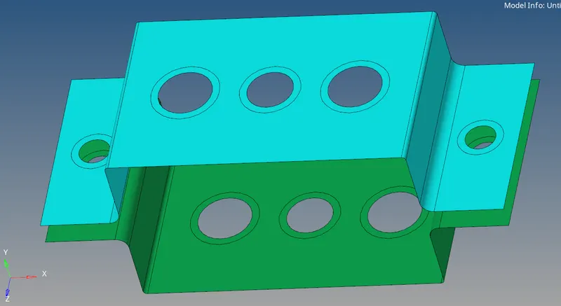
- To create washer splits we have to select the whole and the offset where the washer split has to be created, need to define. Washer split is present in the quick edit section of geometry.
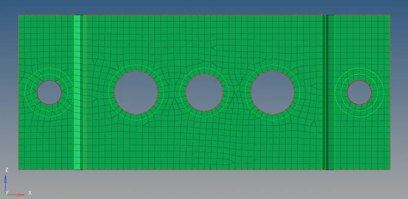
- After providing the washer split the model becomes very easy to mesh, the model is given below.
- To create washer splits we have to select the whole and the offset where the washer split has to be created, need to define. Washer split is present in the quick edit section of geometry.
- Meshing-
- The meshing process involves following steps
- The required meshing type to be done is 2d as the model is a surface type. Then the element requirement is of the mixed type where it is desired to get both quad and tri elements.
- In the 2d section of the toolbar, we have to select the auto mesh option.
- Then to create a mesh for the above surfaces, we have to select the surfaces, give an element size and then provide the required mesh type, in our case it is mixed. Then click on a mesh to create a mesh of the surfaces.
- The required meshing type to be done is 2d as the model is a surface type. Then the element requirement is of the mixed type where it is desired to get both quad and tri elements.
- The meshed body looks like-
- The meshing process involves following steps
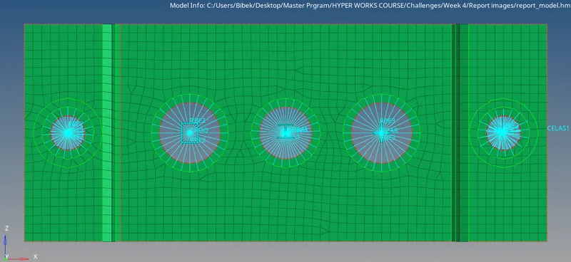
- Creating Rigids(RBE2), Spring and RBE3 links-
- To create an RBE2 link we have to select the 1d section of the toolbar and then select the rigid option.
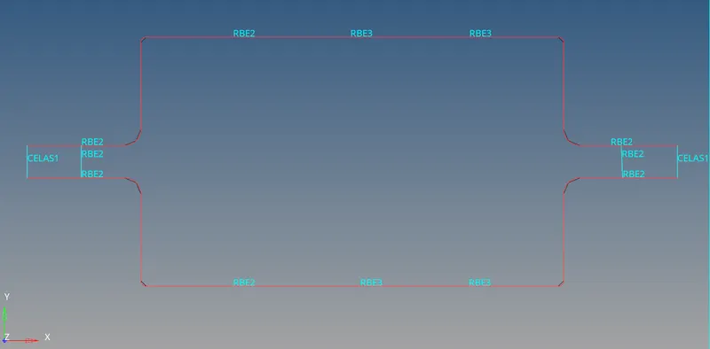
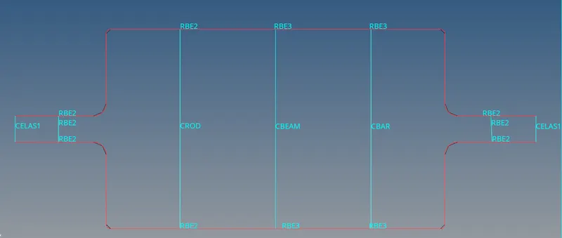
- After creating all the RBE2, RBE3 and Spring links the model becomes
- To create an RBE2 link we have to select the 1d section of the toolbar and then select the rigid option.
- Creating sections of the rod, beam, and bar which is box-section, I-section, and x-section respectively
- Box section for the rod-
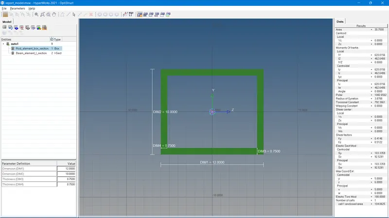
- Select the option Hyperbeam present in the 1-d toolbar, then select section library as OPTISTRUCT and then select cross-section as box section.
- A new hyperbeam window opens and we can assign the respective value of the box cross-section
- Select the option Hyperbeam present in the 1-d toolbar, then select section library as OPTISTRUCT and then select cross-section as box section.
- I Section for the beam-
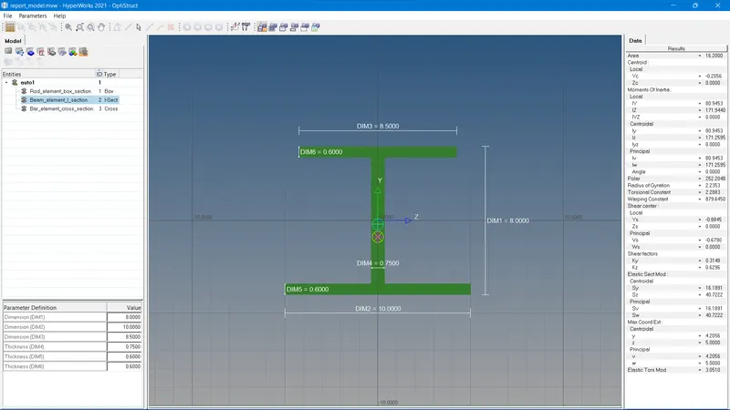
- Select the option Hyperbeam present in the 1-d toolbar, then select section library as OPTISTRUCT and then select cross-section as box section.
- A new hyperbeam window opens and we can assign the respective value of the I cross-section.
- Select the option Hyperbeam present in the 1-d toolbar, then select section library as OPTISTRUCT and then select cross-section as box section.
- X- section for the bar-
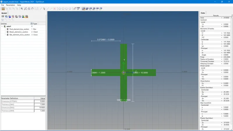
- Select the option Hyperbeam present in the 1-d toolbar, then select section library as OPTISTRUCT and then select cross-section as box section.
- A new hyperbeam window opens and we can assign the respective value of the X cross-section.
- Select the option Hyperbeam present in the 1-d toolbar, then select section library as OPTISTRUCT and then select cross-section as box section.
- Box section for the rod-
- Creating properties of Rod, Beam, and Bar
- Rod-
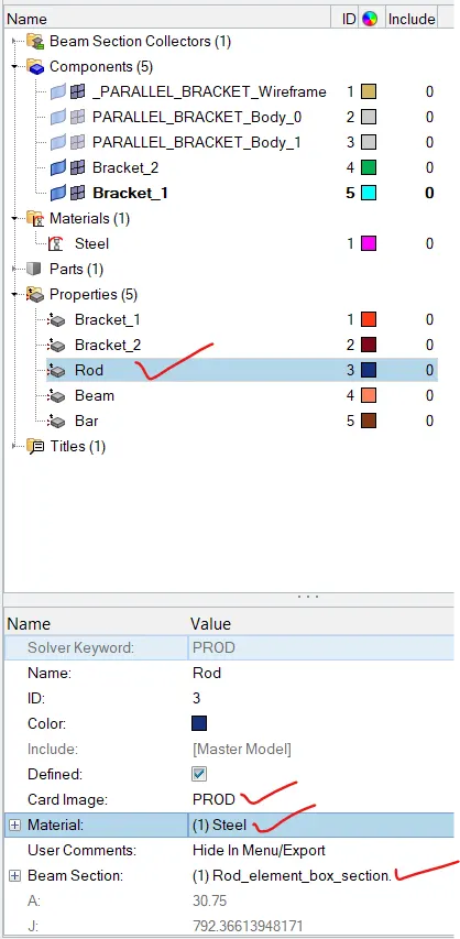
- Assigning the properties to Rod elements.
- Assigning the properties to Rod elements.
- Beam-
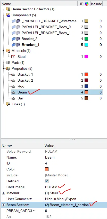
- Assigning the properties to Beam elements.
- Assigning the properties to Beam elements.
- Bar-
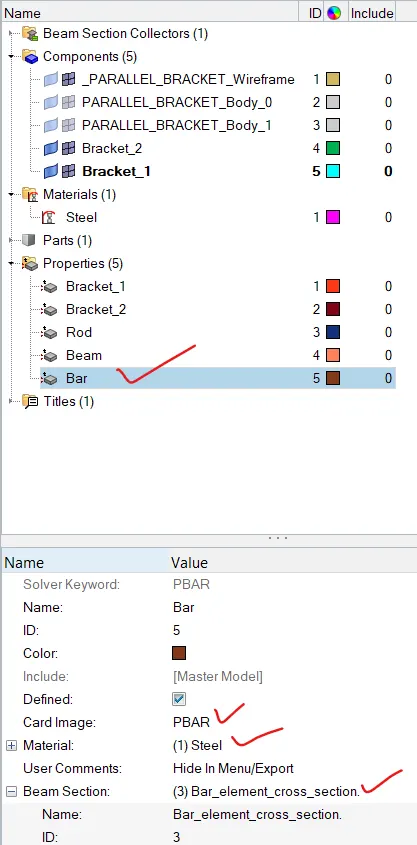
- Assigning the properties to Bar elements.
-
- Assigning the properties to Bar elements.
- Rod-
- Creating Rod, Beam, and Bar and its section with properties
- Both rod and bar are mechanical elements that are only subjected to axial loads whereas the beam can be subjected to any load like torsional, bending, and axial.
- Rod
- A rod needs to be created in the first holes of both the surfaces whose ends are RBE2 links and the dof of the rod element needs to be constrained only translational. Also, the property should be defined as Rod.
- A rod needs to be created in the first holes of both the surfaces whose ends are RBE2 links and the dof of the rod element needs to be constrained only translational. Also, the property should be defined as Rod.
- Beam
- A beam needs to be created in second holes of both the surfaces whose ends are RBE3 links and all the dofs of the beam element need to be constrained. Also, the property should be defined as Beam.
- A beam needs to be created in second holes of both the surfaces whose ends are RBE3 links and all the dofs of the beam element need to be constrained. Also, the property should be defined as Beam.
- Bar
- A bar needs to be created in the first holes of both the surfaces whose ends are RBE3 links and only x and y dof's of the bar element needs to be constrained. Also, the property should be defined as Beam.
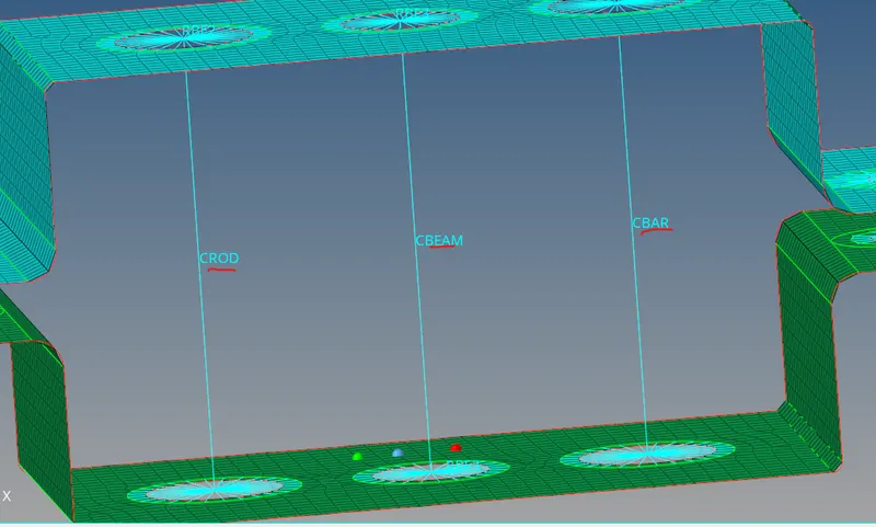
- The figure with all the three 1d elements are given below
- A bar needs to be created in the first holes of both the surfaces whose ends are RBE3 links and only x and y dof's of the bar element needs to be constrained. Also, the property should be defined as Beam.
- Assigning Mass and other properties to the end holes
- Create RBE2 elements in all four end holes of both surfaces. Then create RBE2 links in both holes present in two ends respectively with the opposite surface wholes.
- Select the 1d tool in the toolbar, then select the mass option.
-
- Then create a mass of 10 units in both the RBE2 links.
- Creating springs at both ends
- The two springs are created at both edges of the surface which are named as f in the question.
- Then create spring at both ends of the surfaces.
-
- The model with all the springs and masses is given below
- The two springs are created at both edges of the surface which are named as f in the question.
- Importing the geometry-
- Results:
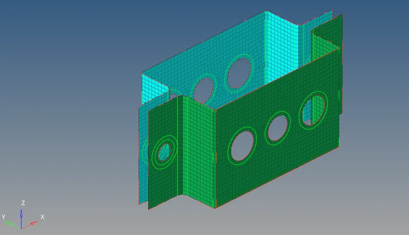
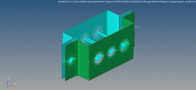
- After enabling all the materials and shaded views the figure looks like as below
-
- After enabling all the materials and shaded views the figure looks like as below