Week 4-1D Element Creation Challenge
Meshing the Given component with the Size of 5 Units
To mesh the given component by using the element size "5", the following steps should be prformed.
- After importing the geometry delete the solid entity which will result in displaying the solid less surface of the given model.
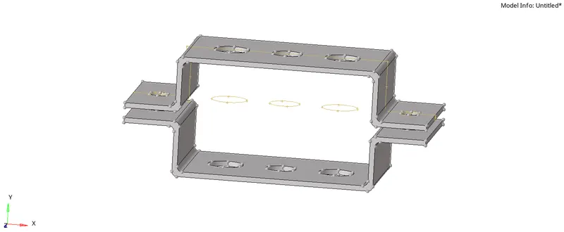
- Perform an Autocleanup by using the "Autocleanup" in the Geometry.
- Create a mid surface by using "Mid Surface" in the Geometry for one of the bracket as shown and lets rename the Mid Surface in the Tab bar as Bracket-1
- Now follow the same procedure for the other bracket in the GA but after creating the new "Component" and renaming it as Bracket-2 in the "Tab bar" as shown.
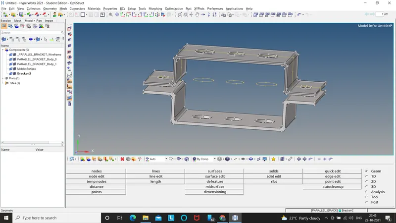
- Delete all the surface entities after creating the mid surfaces, then you will only be left with Bracket-1, Bracket-2 & Mid Surface in the tree of the Tab Bar.
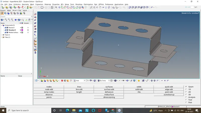
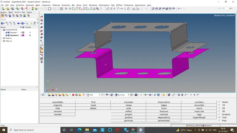
- Now with the help of "Organize" in the "Tools", move the other bracket from the mid surface to Bracket-2 and delete the mid surface from the Tab bar.
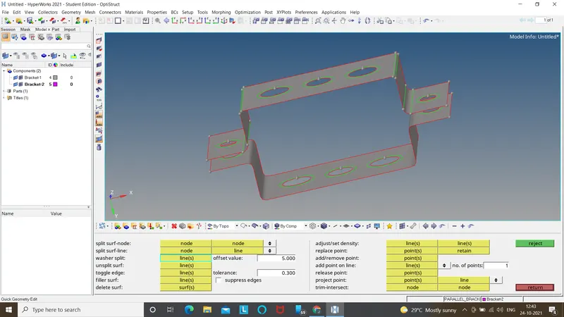
- Go to the "Quick Edit" option in the "Geometry" and create a washer split for the Holes in the bracket(Assuming the Tolerance value as 5).
- Now with the help of "2D" in the main menu page, mesh the brackets w.r.t Mesh type as mixed Element Size of "5" by using Automesh in the main menu bar and in addition try to eliminate the tria elements and rotating quads so the there is no compromise in the mesh quality and simulation time.
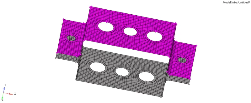
- Hence the meshing with element size "5" is done.
Creating 1D elements on the meshed component as per the given criteria.
a. Rod element.
To create a rod element, follow the given procedure.
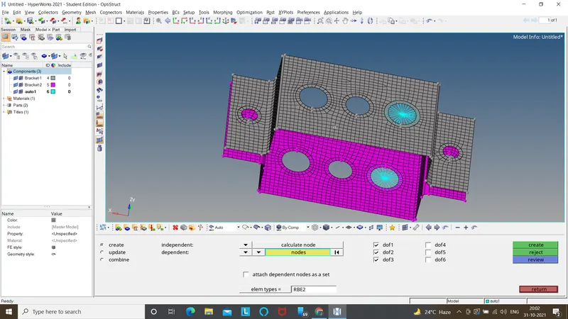
- Choose "1D" in the main menu page, select the "Rigids" in the main menu bar.
- Select "Calculate nodes" in the first row and "Multiple nodes" in the next row as shown in the image.

- When you Left click on the nodes shown in yellow, certain option appears, choose "By path", so that the nodes are selected easily.
- Only select the DOF's 1,2 & 3 as given.
- Finally choose create, then you will find the "RBE2 link" created w.r.t the nodes as shown.
- Follow the same to the other one as per the requirement.
- Select the "Hyper Beam" in 1D(in Main menu page).
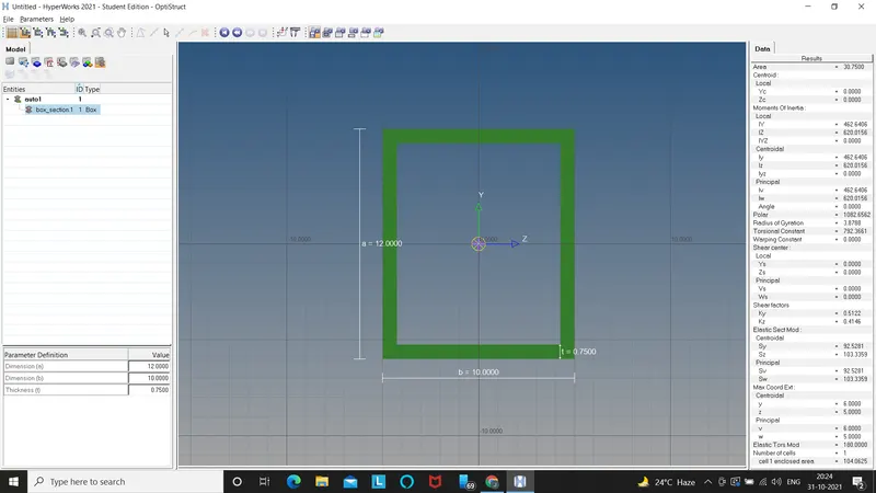
- Choose "Standard Selection", "Hyper beam" & "Thinwalled box" and click on create.

- A window appears as shown, then give the Dimension as per the given data.
- Select "Model view" in the top left of the Tab bar.
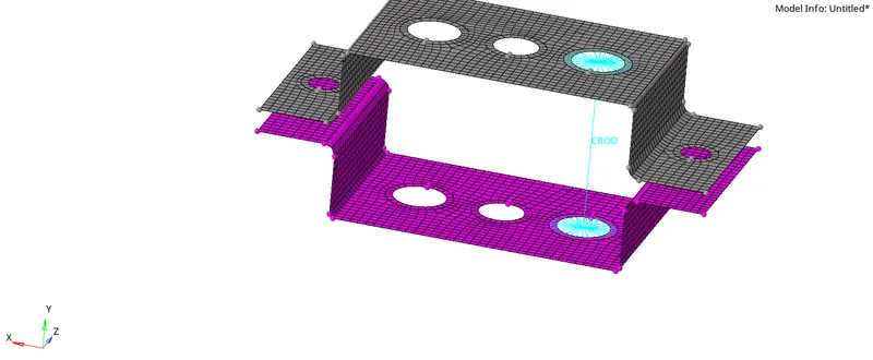
- Select "Rods" in 1D, Select element type as " C Rod", Select the required nodes of the RBE2 link in between which the rod is to be create.
- Now Create "Property" in the Tab bar and rename it as "Rod"
- As shown in the image, An "Entity editor" appears just below the "Tab bar", in that give the "card image" as "PROD" and the "Beam selection" as "Box" which was created earlier.
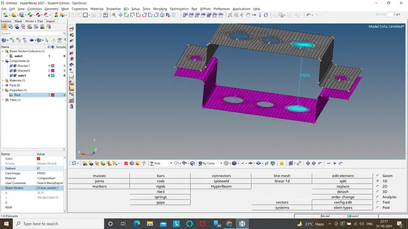
- Go to Rods in the 1D, click on "update" choose the element as CROD, click on property select the "Rod" in it and click on update.
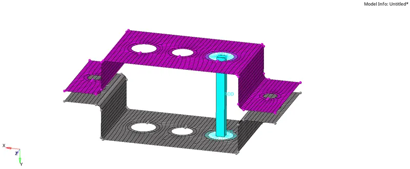
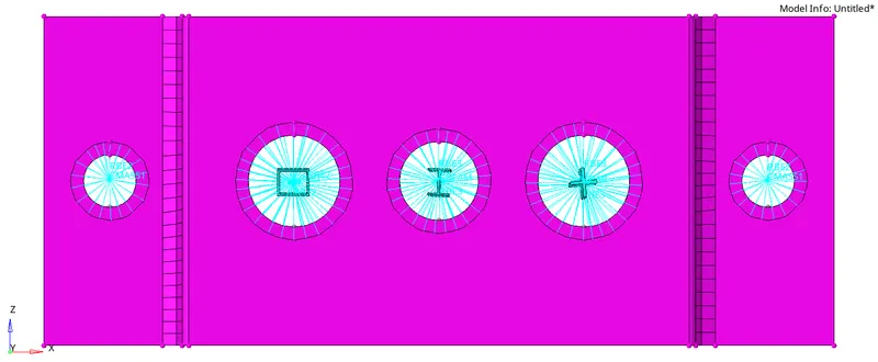
- Therefore to cross verify, Go to the tool bar, which is lying below to the graphical area, click on "1D Traditional an detailed representation" then the cross section of the rod is also seen as shown.
b. Beam element.
To create a Beam element, follow the given procedure.
- Choose "1D" in the main menu page, select the "RBE3" in the main menu bar.
- Select "Calculate nodes" in the first row and select the nodes similarly as done for the RBE2 element.
- Select all the DOFs as shown.

- on clicking create, you will find the RBE3 element created, similarly follow the procedure for other side too.
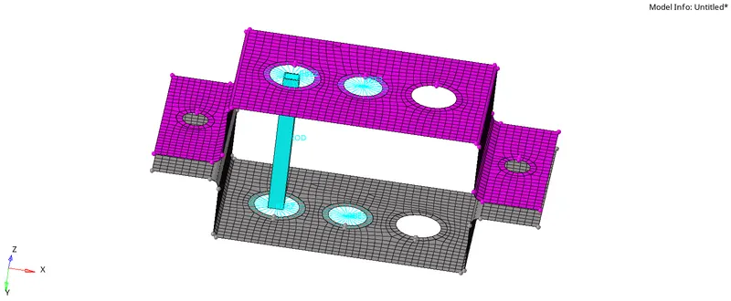
- Select Bar in the 1D, Select element type as "CBEAM", Select the required A, B nodes, Giving vectors to it, the CBEAM appears.
- Select the "Hyper Beam" in 1D(in Main menu page).
- Choose "Standard Selection", "Hyper beam" & "I-Section" and click on create.
- A window appears similarly as in rod case, then give the Dimension as per the given data.
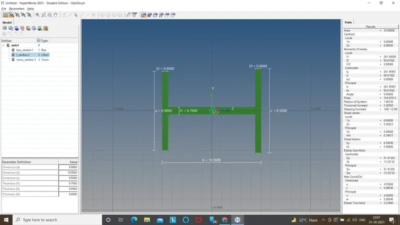
- Select "Model view" in the top left of the Tab bar.
- Now Create "Property" in the Tab bar and rename it as "Beam"
- As shown in the image, An "Entity editor" appears just below the "Tab bar", in that give the "card image" as "PBEAM" and the "Beam selection" as "I-section" which was created earlier.
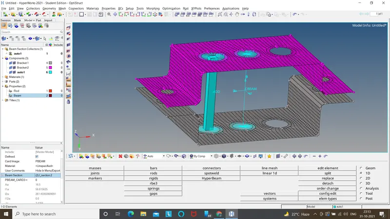
- Go to Bars in the 1D, click on "update" choose the element as CBEAM, click on property select the "Beam" in it and click on update.
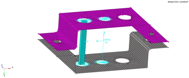
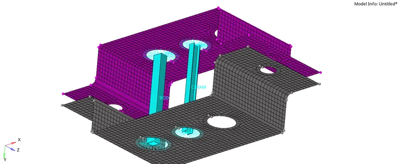
- Therefore to cross verify, Go to the tool bar, which is lying below to the graphical area, click on "1D Traditional an detailed representation" then the cross section of the Beam is also seen as shown.
c. Bar element.
To create a Beam element, follow the given procedure.
- Choose "1D" in the main menu page, select the "RBE3" in the main menu bar.
- Select "Calculate nodes" in the first row and select the nodes similarly as done for the RBE2 element.
- Select the DOFs as shown and given in the Data.
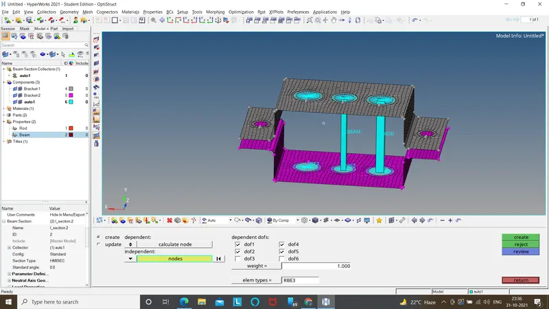
- Select Bar in the 1D, Select element type as "CBAR", Select the required A, B nodes, Giving vectors to it, the CBAR appears.
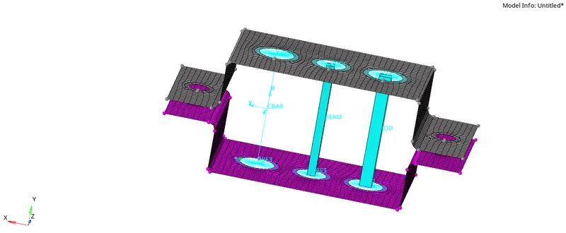
- Go to the "Hyperbeam view" in the top right of the Tab bar, then select "Create" in the entities by right clicking, "Standard sections", "Optistruct" then "Cross"
- Exicute the dimensions as provided.
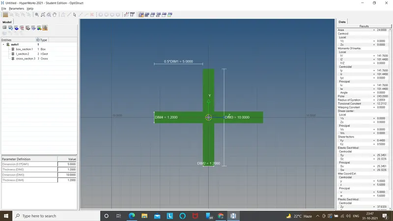
- Select "Model view" in the top left of the Tab bar.
- Now Create "Property" in the Tab bar and rename it as "Bar"
- As shown in the image, An "Entity editor" appears just below the "Tab bar", in that give the "card image" as "PBAR" and the "Beam selection" as "Cross section" which was created earlier.
- similarly update it bar, assigning the properties to it, as we have been doing for previous elements.
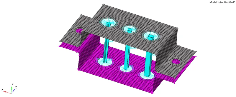
d & e. Applying the mass of magnitude 10 with the RBE2 link
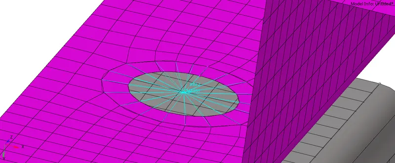
- Create the RBE2 links following the similar process as done previously at required place.
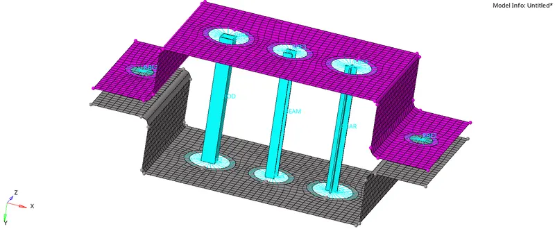
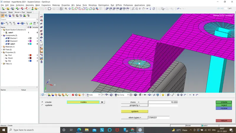
- Select "Masses" in 1D, give the magnitude as "10" , similarly do it for other side(ie..., at 'e' point).
f. Joining the two components with Spring elements.
- Select "Springs" in 1D of the main menu page.
- Select the required nodes in between which you want your spring element to be located.
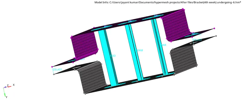
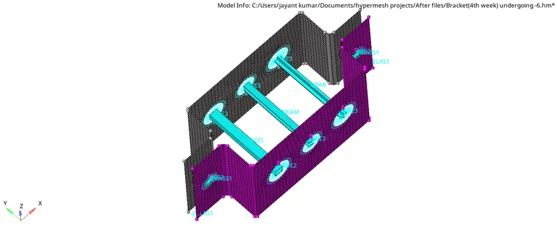
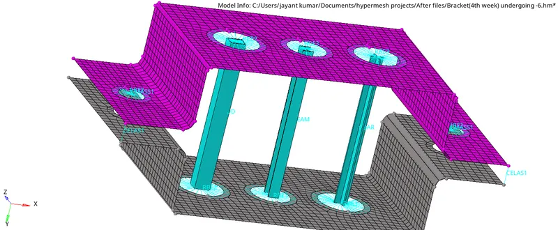
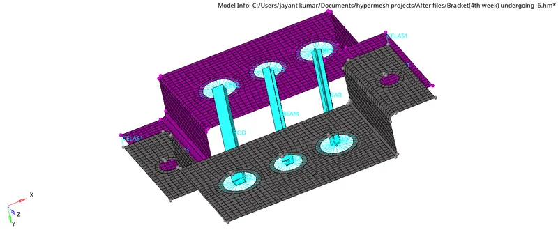
- Hence the final model pictures are shown below.