Week 4-1D Element Creation Challenge
Mesh the Given component with the Size of 5 Units. Create 1D elements on the following component with given cross-section and DOF
First import the file by using the import geometry.
delect the wireframe
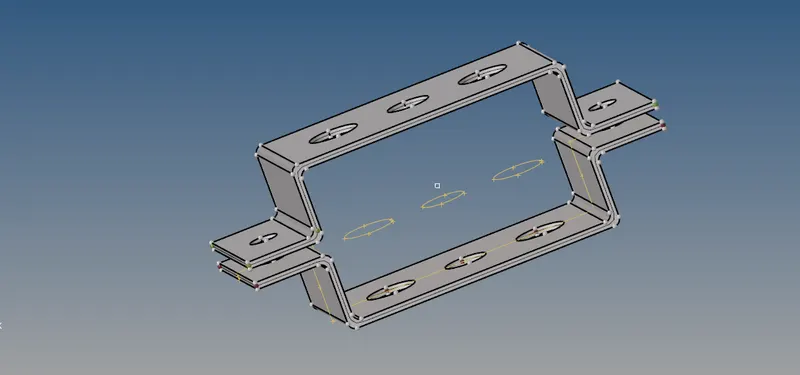
select the grometry and go the mid surface

select the surface upper surface of the body.
retune and remane the middle surface as bracket 1
then do the same opertion to the down surface.
name it as bracket 2
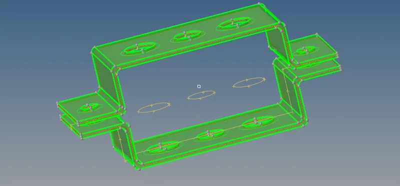
hide the solid surface
you can see the middle surface
you can delect the solid surfaces
surface are showed in the below.
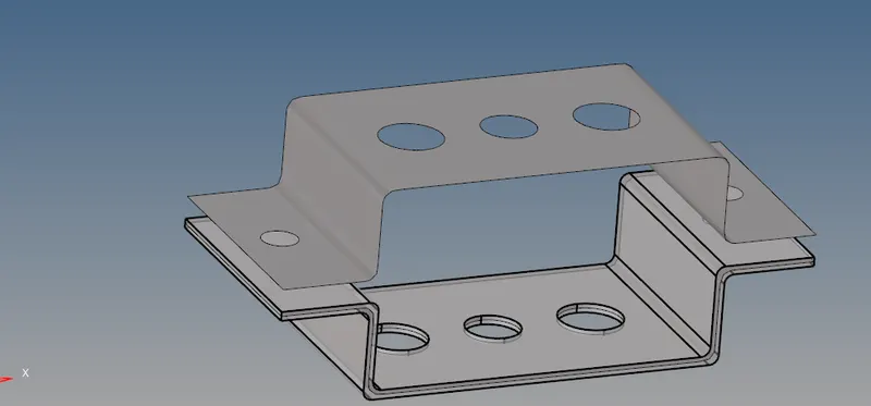
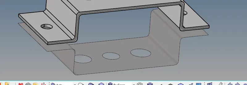
check the geom and select the quick edit.
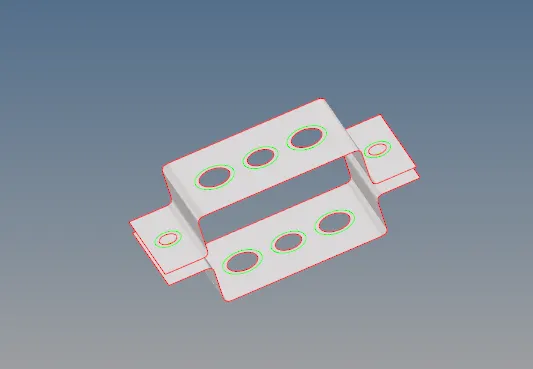
select the circle were required.
offset the circle at the lenght of 5mm.
both figures are showed in the below.
1.
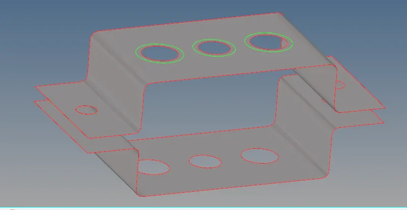
2.

3.
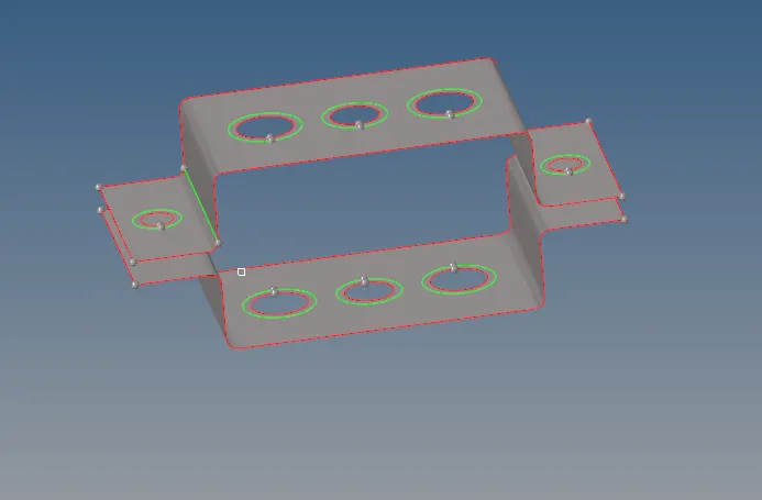
after return form the command.
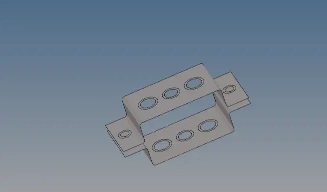
select the 1d and go the auto mesh
select the surface and check the display all surface.
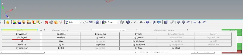
you can see below surface are selected by using the display all
display is used to select the all surface showed on the display.
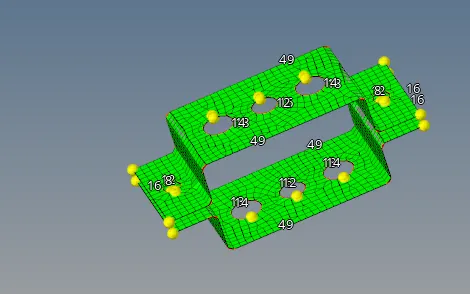
element size is 8mm
mesh type is used mixed.
figure showe in the figure.

after meshing is performed.
to increase nodes by using the right click of the mouse.
to decrease the node use the lift click of the mouse.
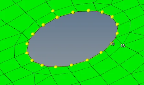
figure showed in the below.
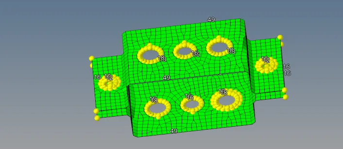
select the rigids
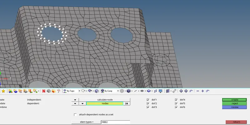
check the multi nodes
check the calculate rode
select the nodes and select the path
handy tool to select the nodes
showed in the fiqure.
do the smilar operation on the opposite side.
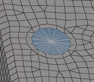
do the same operation on the another side.
select the metrail.

create the properties.
figure showed in the below.
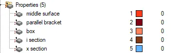
select the material.
and add tickness to the surface.
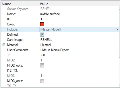
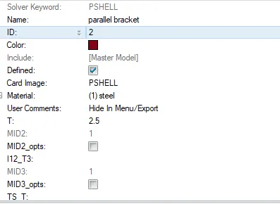
do the same to the parallel bracket.
thickness is 2.5mm and add material also.
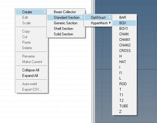
creating the box and i section,x section.
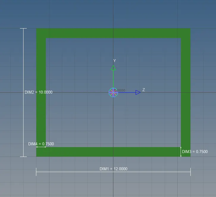
Cross-Section: BOX- Dimension a= 12 mm
dimension b=10 mm
Thickness t= 0.75 mm
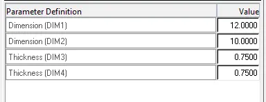
b. Beam element:- All DOF should be constrained with RBE3 link
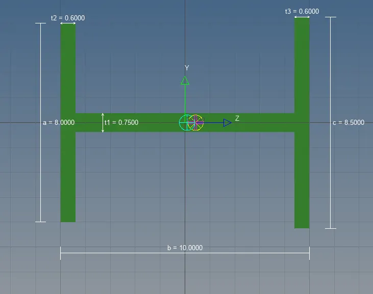
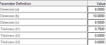
Cross-Section: I Section- Dimension a= 8 mm
Dimension b= 10 mm
Dimension c= 8.5 mm
Thickness t1= 0.75 mm
Thickness t2= .6 mm
Thickness t3= .6 mm
c. Bar element:- Constrain only x and y DOFs With RBE3 link
Cross-section: X section- Dimension DIM1= 5 mm
Thickness DIM2= 1.2 mm
Dimension DIM3= 10 mm
Thickness DIM4= 1.2mm
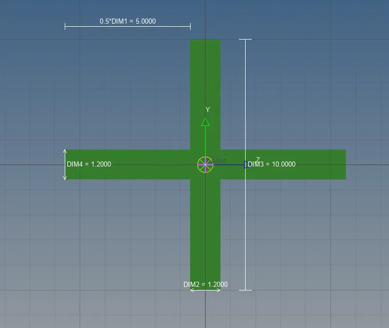
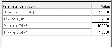
if need to edite do and select the hyperbeam view.
icon is highlighted in below figure.

update the elements.
select the rigids and check the updates.
select the elements and select the nodes.
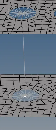
after updating the surface elements showed in the figure.
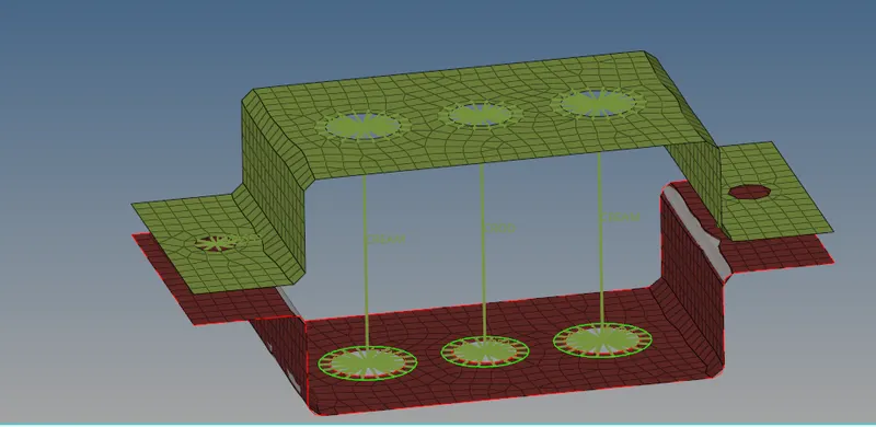
select the element
select the type of element.

go to perporties
select the box and card image change in tp PBAR.
BEAMSECTION AS TO BOX SECTION.
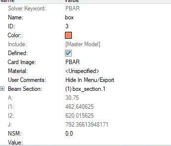
select the i SECTION properties change the card image
select the beam section i section.
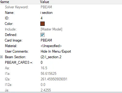
for X section do the same operation.
how see the box and i,x sections?
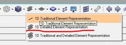
activate the 1d detailed element respresention then you see the box pillar and i and x section on the display.
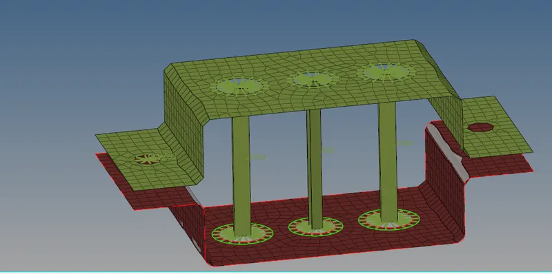
d. & e. Apply the mass of magnitude 10
create the node by using the rigids.
select the mass
select the node and apply the mass of 10mm.
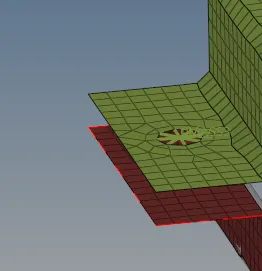
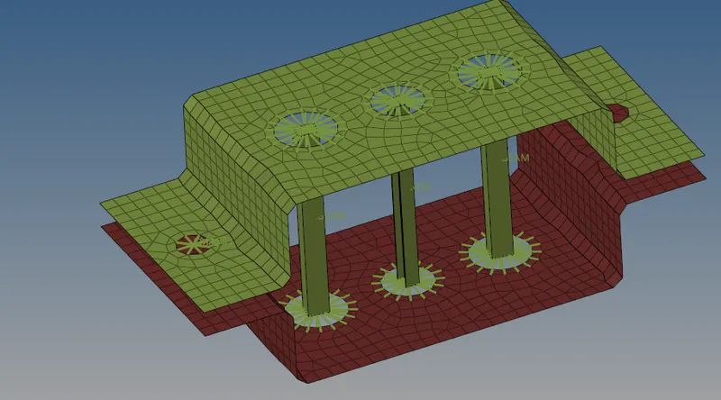
FINAL OUTPUT: