Week 4-1D Element Creation Challenge
TO CREATE 1D ELEMENT ON A PARALLEL BRACKET BY USING HYPERMESH
AIM: To mesh the parallel bracket and then to create 1D elements with given cross-section and DOF using hypermesh.
OBJECTIVE:
- To extract middle surface.
- To discretize the 3D CAD model using given target element size.
- To create RBE2 and RBE3 link at respective reference place of a,b,c,d,e and assign spring element with reference to place f.
- To create Box, I and cross sections using hyperview.
- To create rod element with translational DOF and assigning cross-section is BOX section.
- To create beam element with all DOF and assigning cross-section is I section.
- To create bar element with x and y DOF and assigning cross-section is CROSS section.
- To apply the mass magnitude at independent node of RBE2 link with reference position d and e.
PROCEDURE:
- CAD MODEL:
First we have to import the required file i.e. PARALLEL_BRACKET, which is in IGS format. So to import the IGS model in hyperworks we have to follow File--->Import---->Geometry---->File type: IGES---->select file--->Import. Once model is opened, it will look like as shown in picture below.
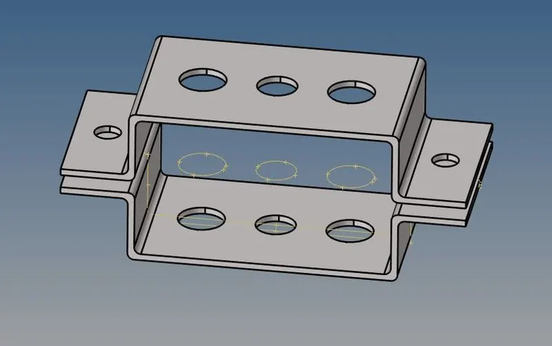
Figure 1: CAD model of PARALLEL_BRACKET
We have to assume the annotations reference for each hole as shown in picture below.
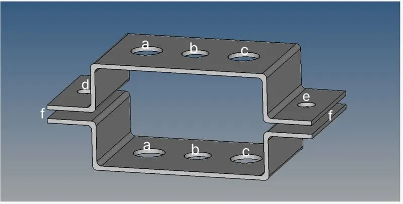
Figure 2: Annotations for CAD model of PARALLEL_BRACKET
- Mid Surface Extraction:
Mid surface is the surface between two surfaces. If thickness of component is uniform throughout then mid surface generates proper. Mid surface helps to reduce number of nodes and elements created on the surface. Which in turns helps to reduce storage space required to store entire component as well as also reduce the processing time required to analyze the entire component.
To extract the mid surface from upper bracket. We have to follow: Geometry---->midsurface---->auto mid surface---->Select surface i.e. upper bracket---->extract.
Same procedure we have to follow to extract middle surface on lower bracket. Once mid surface is created, we will rename upper bracket as “Bracket_1” and lower bracket as “Bracket_2”. Now we have to delete solid part from geometry. Extracted mid surface is look like as shown in picture below.
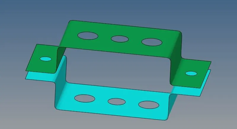
Figure 3: Mid surface extraction
To move the mid surface to Bracket_2. We have to follow:
Tool---->organize---->collectors---->select surface--->dest component: Bracket_2---->move.
- Geometry cleanup
To perform geometry cleanup operation, we will use autocleanup panel. Cleanup operations include the equivalencing of "red" free edges, fixing of small surfaces (relative to the element size), and detection of features such as beads. It also performs specified surface editing/defeaturing operations like the removal of pinholes (less than specified size), removal of edge fillets, and the addition of a layer of washer elements around holes.
The criteria by which the cleanup functions are determined by the BatchMesher parameter and element quality criteria files, both of which can be edited from within this panel using the BatchMesher Parameter Editor. Auto cleanup operation helps to prepare our model for meshing based on parameters set in BatchMesher criteria file.
To perform this operation, we have to follow:
Geometry---->autocleanup---->select surface: all---->autocleanup
Once operation is done, model will look like as shown in picture below.
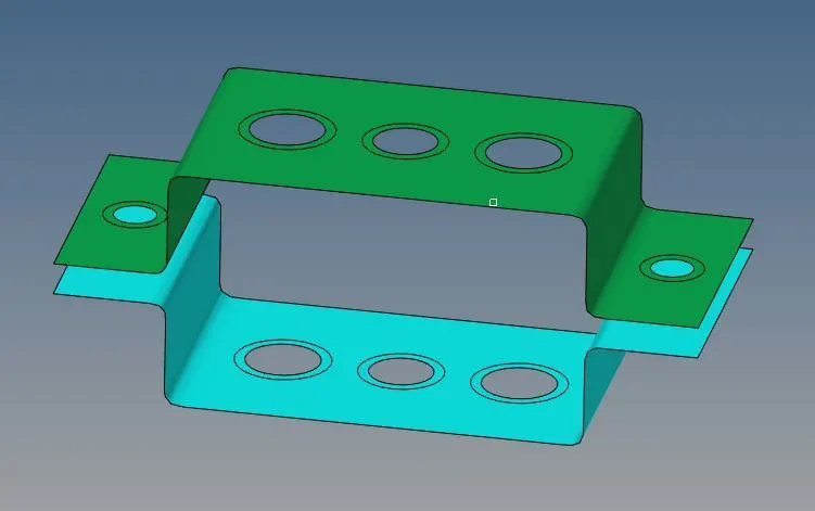
Figure 4: Geometry cleanup
- Discretization of component:
A mesh is a network that is formed of cells and points. A meshing is the process of subdividing the structure from infinite number of points to the finite number of node and elements. This process is also known as discretization.
And we have to maintain the distance between two nodes equal to the average target length i.e. 5mm. This can be done by following certain steps i.e.
2D---->automesh---->select surface---->element size---->mesh type: mixed---->mesh.
Once discretization is done model will look like as shown in picture below:
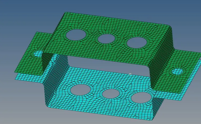
Figure 5: Discretization of PARALLEL_BRACKET
- Create 1D elements
5.1 Creating RBE2 and RBE3 links
5.1.1 For better understanding, first of all we will annotate a,b,c,d,e and f at each hole as shown in picture below.
Figure 6: Annotations for CAD model of PARALLEL_BRACKET
5.1.2 Now we have to create RBE2 links with translation degree of freedom(DOF) in x,y and z direction at reference point a under rigid element panel. To create link we need to select nodes around the holes by path. Once link is created at both reference point a we have one independent node.
[Command: 1D---->rigids---->create---->independent node: calculate node----> dependent node: multiple nodes (selection by path) ---->create.
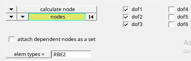
Figure 7: Degree of freedom at "a"
Element selection as shown:
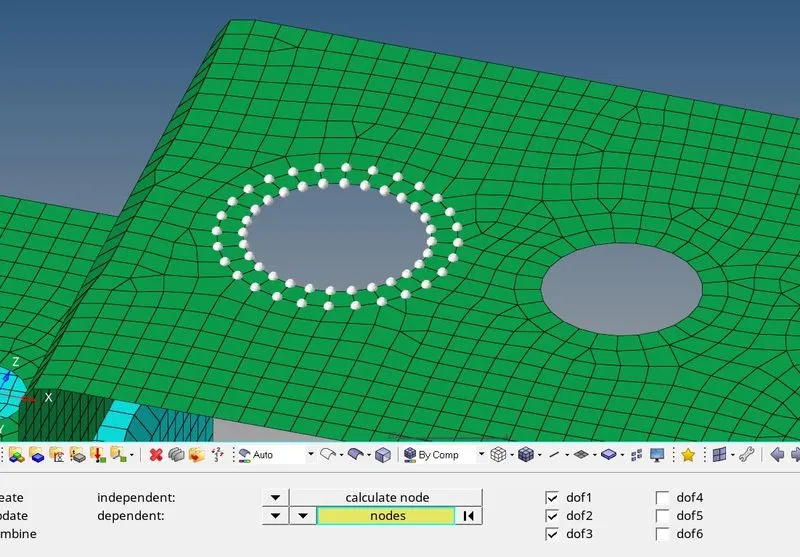
Figure 8: Element selection
5.1.3 Similarly we will create RBE3 link at reference point b with all DOF should be constrained.
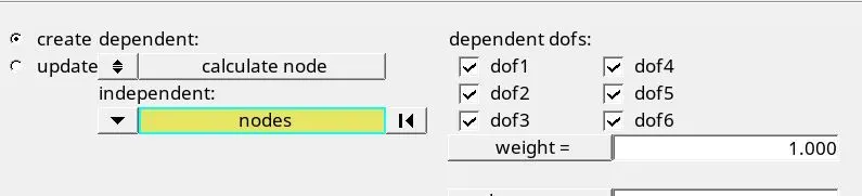
Figure 9: Degree of freedom at "b"
5.1.4 Now we will create RBE3 link at reference point c with constrains only x and y DOF.
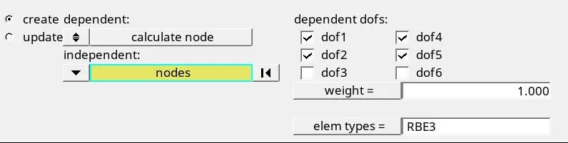
Figure 10: Degree of freedom at "c"
5.1.5 Now we have to create RBE2 links at reference point d & e and also have to apply mass magnitude of 10.
once all links are assigned model will look like as shown in picture below:
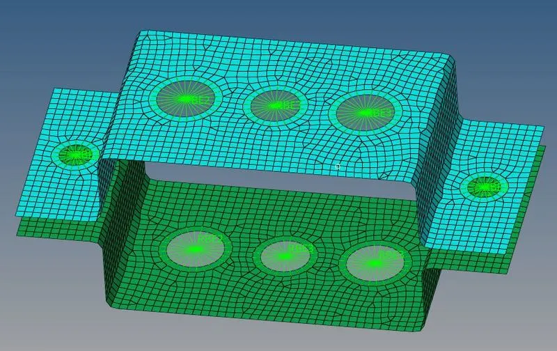
Figure 11: Links assigned on PARALLEL_BRACKET
5.2 Creating the elements
5.2.1 Now at reference point a rod element has to create in order to connect two rigid links of RBE2. A rod element is an element created in a space between two nodes of a model where rod elements are desired. [Command: 1D---->rods----> create and select both independent nodes----> property: Rod---->element type: C ROD---->OK]
5.2.2 Similarly we have to create beam element at reference point of b with element type: CBEAM.
5.2.3 Now we have to create bar element at reference point of c with element type: CBAR.
5.2.3 Now we have to create spring element at reference point f with translation dof 1 in order to connect bracket_1 and bracket_2. [Command: 1D---->springs---->create and select nodes---->element type: CELAS1---->ok.
Once all elements are created model will look like as shown in picture below.
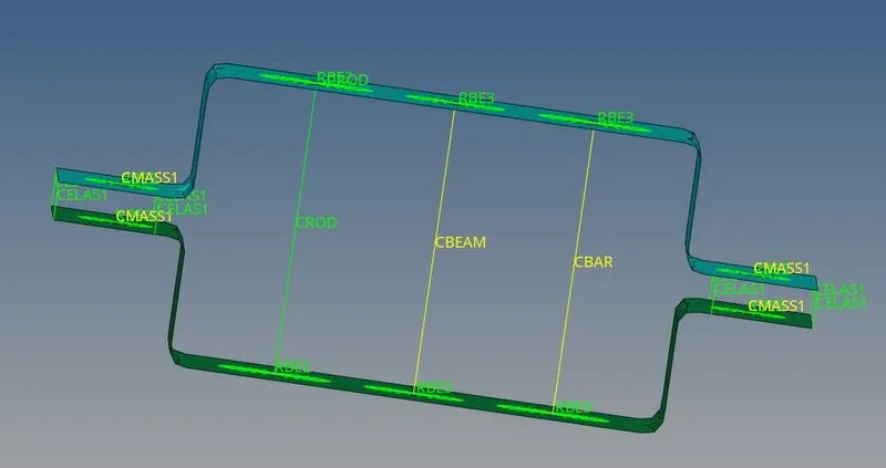
Figure 12: Creating the elements on PARALLEL_BRACKET
5.3 Cross-section in HyperBeam:
To use HyperBeam we need to select 1d---->HyperBeam---->generic section---->create
Now we have to create different cross-section such as Box, I and X section for element types Rod, Beam and Bar elements.
5.3.1 Cross-Section Box:
Dimension a= 12 mm
dimension b=10 mm
Thickness t= 0.75 mm
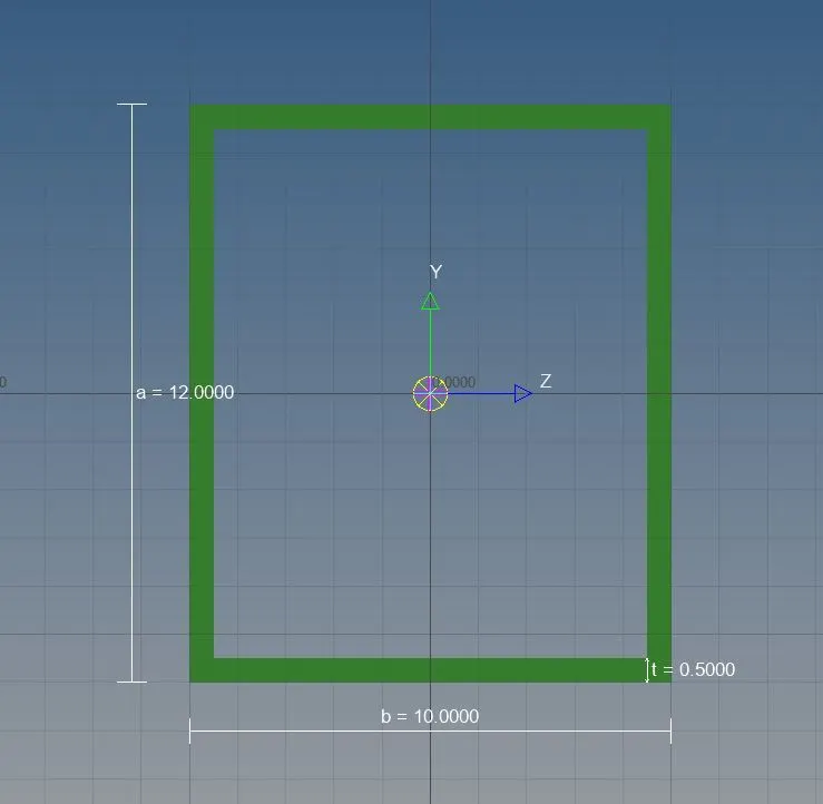
Figure 13: Cross-Section Box
5.3.2 Cross-Section I:
Dimension a= 8 mm
Dimension b= 10 mm
Dimension c= 8.5 mm
Thickness t1= 0.75 mm
Thickness t2= .6 mm
Thickness t3= .6 mm
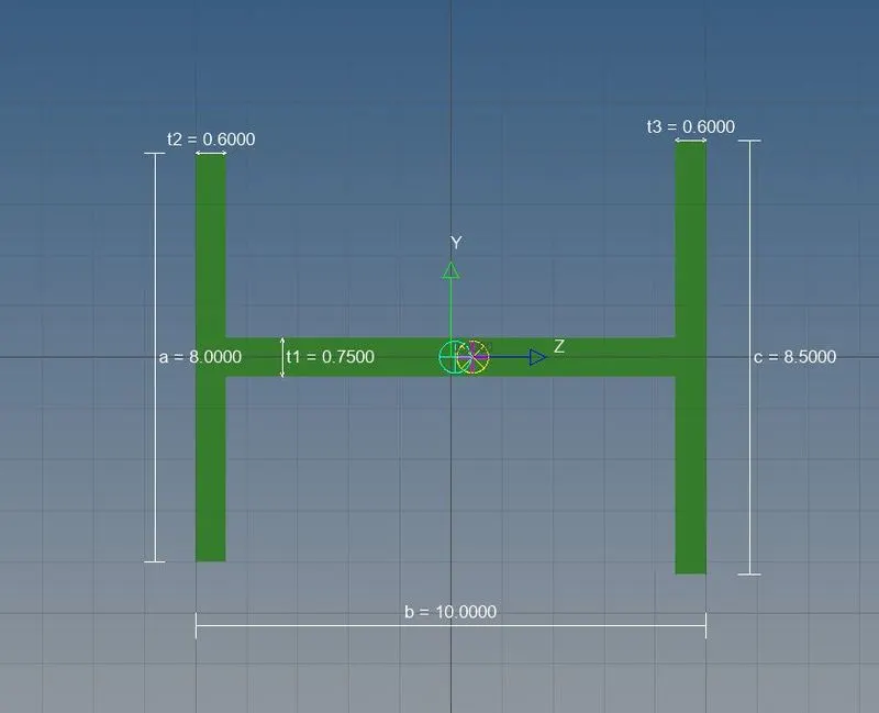
Figure 14: Cross-Section I
5.3.3 Cross-section: X section-
Dimension DIM1= 5 mm
Thickness DIM2= 1.2 mm
Dimension DIM3= 10 mm
Thickness DIM4= 1.2 mm
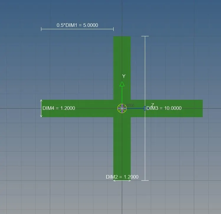
Figure 15: Cross-Section X
Assigning property to elements
Now we have to create properties for each element i.e. Rod, beam and bar elements.
In model view we have to right click on properties then click on create and rename the property i.e. Rod. Similarly, we have to create property for beam and bar.
ROD Card Image: PROD Beam Section: Rod
BEAM Card Image: PBEAM Beam Section: Beam
BAR Card Image: PBAR Beam Section: Bar
Now we have to update for respective elements, for rod we will follow
Rod---->update---->property: select rod---->update
Similarly, we have to update properties for Beam and Bar.
For 3D representation of these created elements, we have to switch 1D Traditional element representation to 1D Detailed element representation.
Similarly, to show shell element as thick we have to switch 2D Traditional element representation to 2D Detailed element representation.
- Result and Conclusion
Mid surface and meshing is done successfully on 3D CAD model of PARALLEL_BRACKET. Then 1D elements are created successfully with given cross-section and DOF.
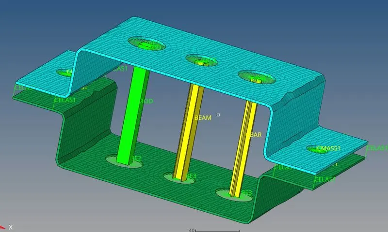
Figure 16: 3D CAD model of PARALLEL_BRACKET