Meshing and Creating 1D Element
AIM:
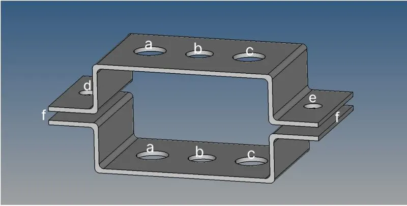
The main objective of the Challenge is to mesh the given component called Bracket with a target length of 5mm and to make the 1D elements like Rod, Beam, and Bar with the given cross-section and D.O.F(Degrees of freedom) by using the Hypermesh software.
GIVEN DATA:
a)Rod Element:
- Translational DOF should be constrained with RBE2 link
- Cross-section: Box
- Dimension, a=12mm
- Dimension, b=10mm
- Thickness, t=0.75mm
b)Beam Element:
- All DOF should be constrained with the RBE3 link
- Cross-section: I-section
- Dimension, a=8mm
- Dimension, b=10mm
- Dimension, c=8.5mm
- Thickness, t1=0.75mm
- Thickness, t2=0.60mm
- Thickness, t3=0.60mm
c)Bar Element:
- Constrain only X and Y DOF with RBE3 link
- Cross-section: X-section
- Dimension, DIM1=5mm
- Dimension, DIM2=1.2mm
- Dimension, DIM3=10mm
- Dimension, DIM4=1.2mm
d&e)Apply the mass of magnitude 10 with the RBE2 link:
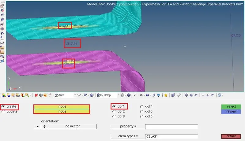
f)Join the components with spring Elements:
PROCEDURE:
👉 Selecting Solver:
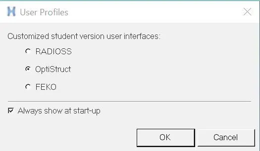
- Selecting the type of solver to which we are working to model the bracket, so we choose OptiStruct as solver because It is an implicit solver used for static and durability problems.
- RADIOSS and FEKO are some of the other solvers from Altair.
👉 Import the Model:
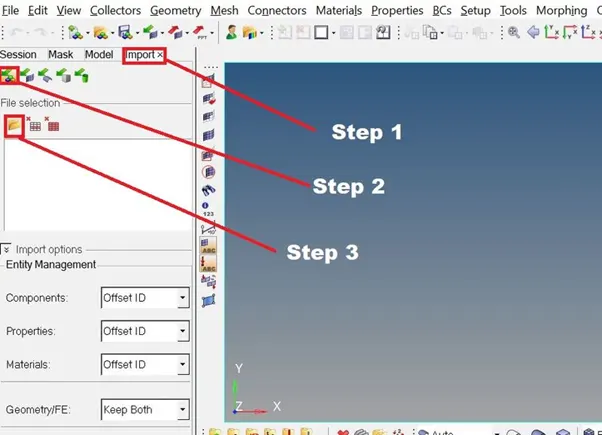
The HyperWorks offers various options for importing and exporting any model the options present in the import and export menu are the same. The following option is present,
- Import Model
- Import Solver Deck
- Import Geometry
- Import BOM
- Import Connectors
The following steps are present in the TAB area,
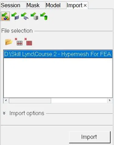
- Import >>> Import Model >>> Select files
👉 Mid-surfacing:
Mid-surfacing modeling is a technique for creating a simplified shell representation of a solid model. It can reduce the computational expense of analyzing a complete solid when a shell mode with a defined thickness and fewer details is suitable for the required analysis.
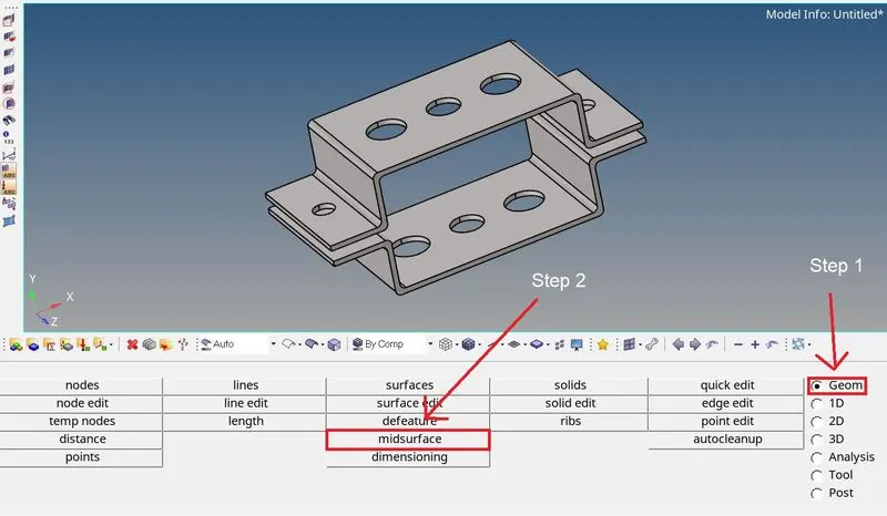
- From the Geom pages >>> Select the Mid-surface from the panel
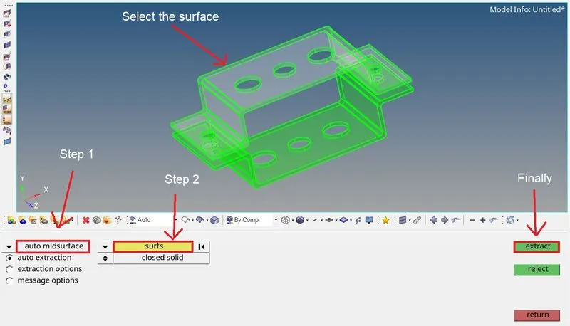
- Select auto midsurface >>> auto extraction method >>> select the surf
- Click the surface, then it will whiten the color then click extract to get the mid surface
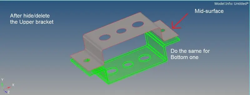
- Delete/Hide the bracket from Browser >>> Componenets >>> Parallel brackets body tp see the midsurface clearly
- Do the same thing for the bottom surface too.
👉 Add/Delete Component:
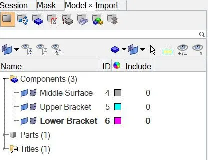
- In the browser menu, we see the components list are present
- We can edit/delete/add/rename it
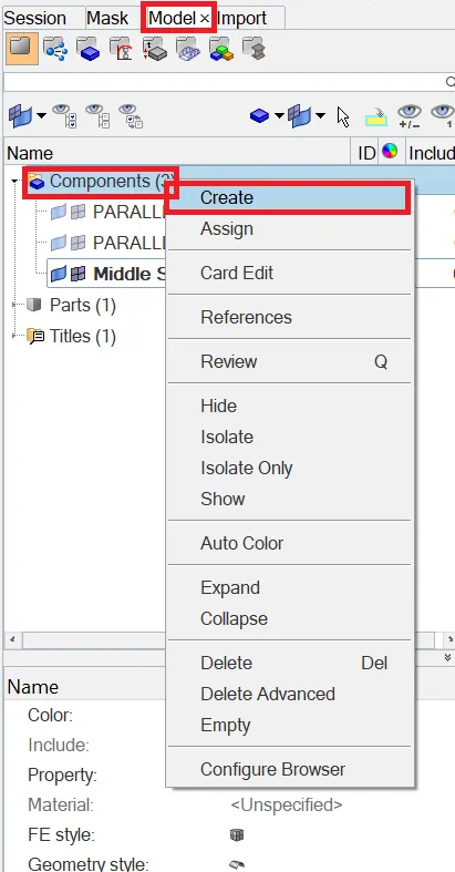
- From the model tab, we can right-click the component bar to get more actions buttons
- Here, we can make the changes
- Create two components and name as Upper bracket and lower bracket
- Delete both solid parts named as parallel blocks
👉 Organize:
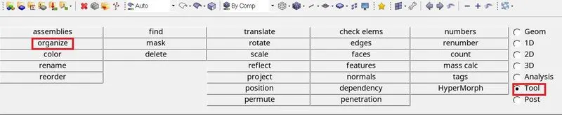
Organize panel is used to re-organize the database by copying or moving data(entities) among collectors, includes, or parts.
- Tools >>> Organize
- Organize >>> Collectors >>> surfs
- Select the surface and choose the component to assign and we can change color as per the wish
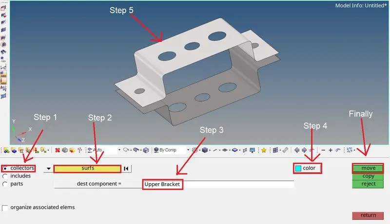
- Use the collector subpanel to organize entities such as elements, loads, and system into their corresponding components, load collectors, system collectors, and so on.
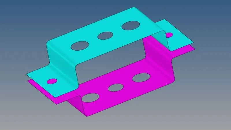
- Do the same thing for another bracket also and use the return to get back home
👉 Washer cut:
- Creating a washer cut is used to seat on a hole in our model
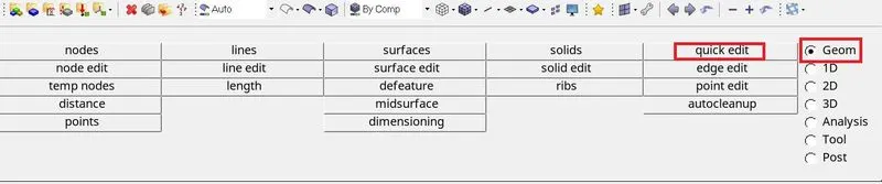
- Geom >>> Quick edit
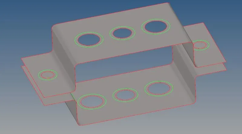
- Add a circular edge around a hole in a surface which is mostly used for creating all quad mesh around a hole
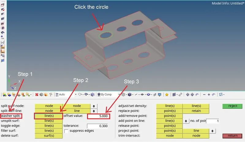
- Select the lines and give an offset value as 5
- perform the actions for both brackets
👉 Meshing:
Meshing is a part of the simulation process where complex geometries are divided into simple elements that can be used as discrete local approximations of the larger domain. The mesh influences the accuracy, convergence, and speed of the simulation.
- Automesh option is used for meshing a surface with 2D elements
- Change Geom mode as 2D in the Mainmenu bar
- Then select the Automesh option
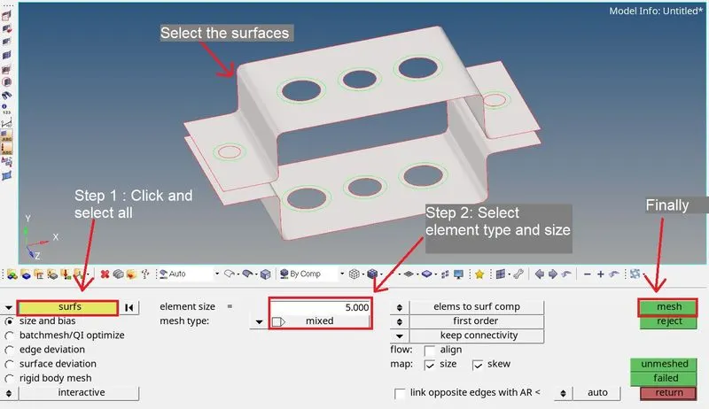
- Click the surf option and select the 'all' option
- Input the mesh element size as '5' and type as 'mixed'
- Then check once whether all the inputs are correct
- Then click mesh to perform the meshing on the component
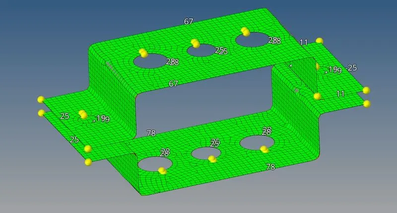
- After meshing, Some of the areas like holes are not meshed properly, so that we can make the adjustment by adding and subtracting the density of the edge by using the Right and left mouse button
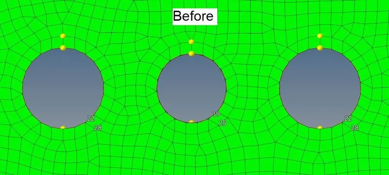
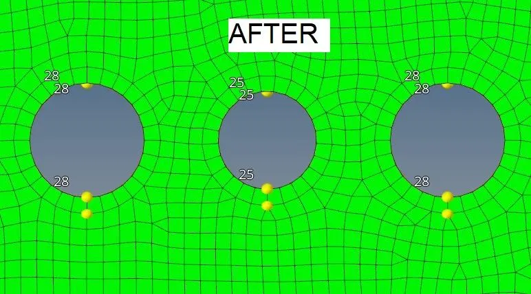
- Here, In the first image, the count of the washer cut has different so the mesh was not good
- After performing some actions, now the mesh is good and the flow looked solid, this will help smooth simulation
- Performing this same action throughout the model to get the perfect mesh.
👉 Assign Property & Material:
Assign the property and the material to an element is very important, the property is the trump card of the object which can hold the answer for the thickness, material type, and so on
- In the Browser tree, right-click the mouse and select the property to create the property tree in the browser
- Name the property tab as Upper and Lower bracket
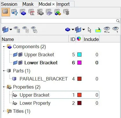
- Then do the same steps to make the material tree and name as steel
- Click the upper/lower property, which makes the new tab just below the browser tree which is used to make changes like color, material, and thickness
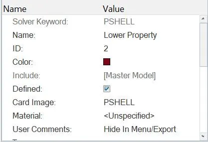
- Specify the material as steel by selecting the material note
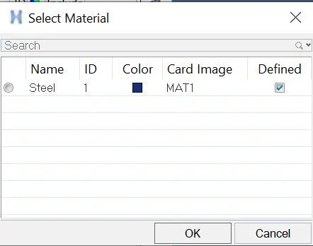
- Select the option and click ok
👉 1D Elements:
All line elements which has two nodes to form a line, whether straight or curved called the 1D element. They have translational and rotational displacement functions.
1) Creating RBE2/Rigid element:
The RBE2 element can be used for connecting two nodes to model a 'rigid' welded type connection with 3 translational DOFs. The RBE2 element can also be used to model a wagon wheel type connection between the independent and the dependent nodes
- Go the 1D >>> Rigid
- create an RBE2 by selecting the nodes by using the path mode
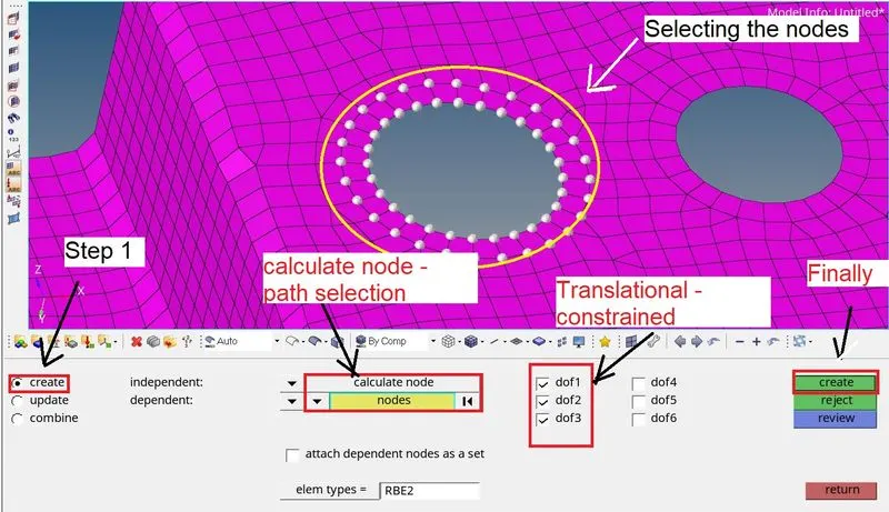
- Change select node into calculate node, then only we use the path mode for selecting nodes
- Translational DOF's only should be constrained then create the RBE2 connection in both brackets at 'a' reference
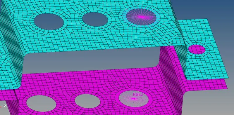
2) Creating RBE3 element:
The motion at the dependent node is a weighted average of the motion at the independent nodes. This is why it is also known as an interpolation R element. RBE3 elements do not add artificial stiffness to the structure like RBAR or RBE2 elements.
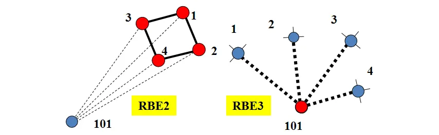
- Go the 1D >>> RBE3
- create an RBE2 by selecting the nodes by using the path mode
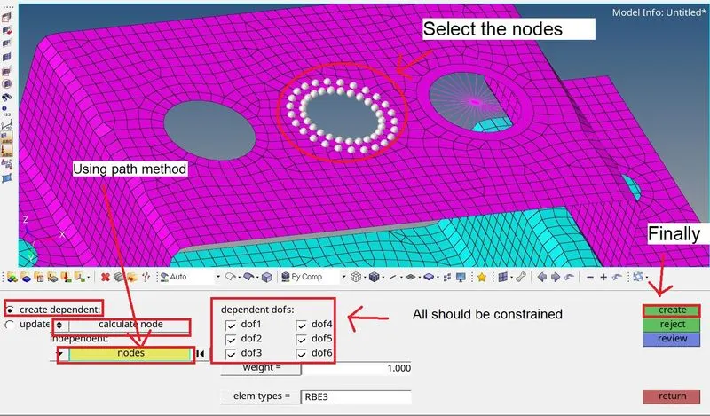
- Change select node into calculate node, then only we use the path mode for selecting nodes
- All DOFs should be constrained then create the RBE3 connection in both brackets at 'b' reference
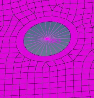
- Do the same RBE3 element for reference 'c' but the Constraint only 'x' and 'y' DOFs only

- For 'd' and 'e', input the mass of magnitude as 10 with RBE2 link
- 1D >>> Mass
- select element type as CMASS and mass as 10, pick the node as RBE2 node, and create.
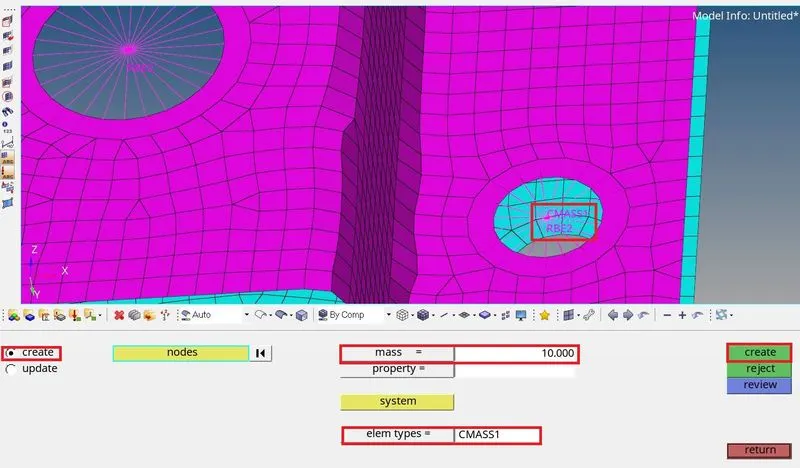
- Create a new component as 'special' for the RBE2 & RBE3 elements, so that we can identify easily.
Six degrees of freedom:
a. Translational movement
- X-axis(dof1), Moving forward and backward is called surging
- Y-axis(dof2), Moving upward and downward is called heaving
- Z-axis(dof3), Moving left and right is called swaying
b. Rotational movements
- XY axis(dof4) - Moving between X and Y-axis is called pitch
- XZ axis(dof5) - Moving between X and Z axis is called yaw
- ZY axis(dof6) - Moving between Z and Y axis is called roll
3) Creating Rod, Beam, and Bar:
BAR:
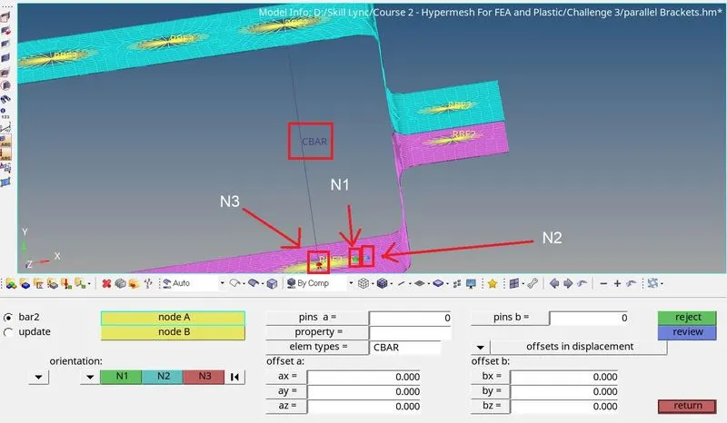
- From 1D elements >>> bars
- Then select the two nodes and select the element type as 'CBAR'
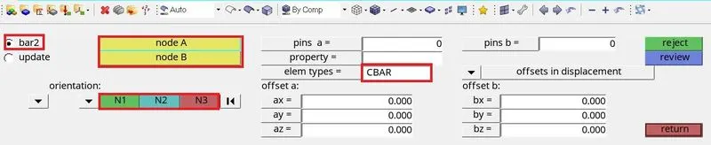
- Select the top and bottom node of reference 'c' and select the N1, N2, and the N3
- then click enter or Middle mouse button to perform
- Create a new property named BAR and Card name as 'PBAR'
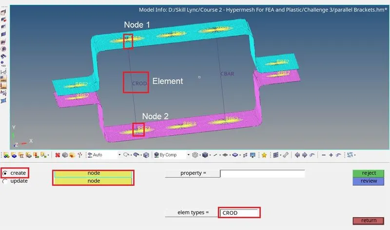
ROD:
- For making Rod, same in 1D element >>> Rod
- For the rod, we have selected Node 1 and 2 to create & select the element type as 'CROD'
- Create a new property named ROD and select the Card name as 'PROD'
BEAM:
- For beam 1D element >>> Bar
- Then select the two nodes and select the element type as 'CBEAM'
- Create a property name as BEAM & card name as 'PBEAM'
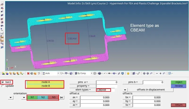
- Select the top and bottom node of reference 'b' and select the N1, N2, and the N3
- then click enter or Middle mouse button to perform
SPRING:
- For spring 1D elements >>> Spring
- Select the node from the reference of d & e and select the element type as CELAS
- Create a new property as SPRING & card name as 'PELAS'
- Input the mass of magnitude as 10 by 1D >>> mass
- Input the mass as 10 and select the node ( RBE2 Reference from d&e) and element type as CMASS1

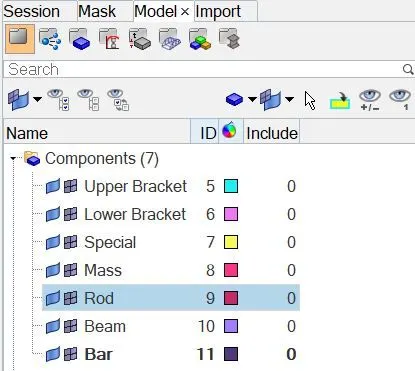
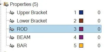
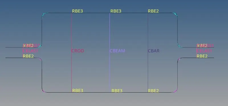
Assign separate component for every 1D element like below:-
👉 CROSS-SECTION:
1) For ROD:
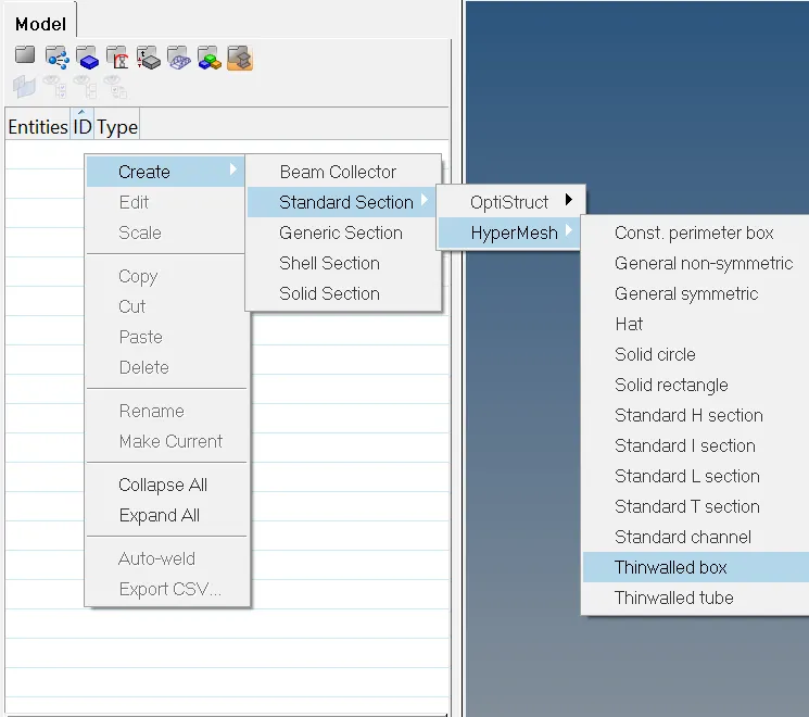
- Go to hyperbeam view >>> Create >>> Standard selection >>> Hypermesh >>> Thinwalled Box
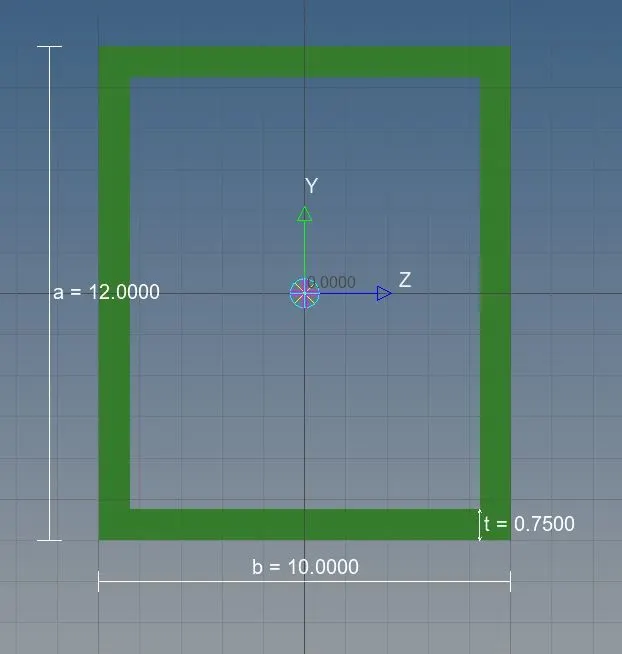
- Cross-section as BOX
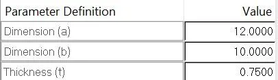
- Dimension, a=12mm
- Dimension, b=10mm
- Thickness, t=0.75mm
2) For BEAM:
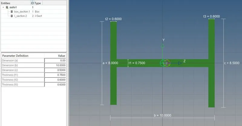
- Go to hyperbeam view >>> Create >>> Standard selection >>> Hypermesh >>> Standard I Section
- Cross-section as I
3) For BAR:
- Go to hyperbeam view >>> Create >>> Standard selection >>> Optistuck >>> Cross
- Cross-section as X
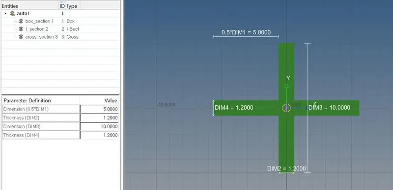
- Properties and the card name has been assigned as per the above procedure
- Select the cross-section for the property as per the requirements
- Change the 1D traditional representation element into the 1D detailed element representation in the display bar and same as 2D
RESULT:
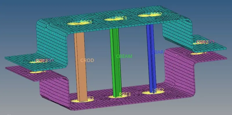
The Given parallel bracket has meshed with an element length of 5mm and the 1D elements have been created as per the reference and also the Cross-section and DOF has been assigned properly.
Google Drive link:
https://drive.google.com/file/d/1q8KkCGftPesy2TijeCJu1oLSqLmKzI_4/view?usp=sharing