Week - 4
CHALLENGE-4
1)
AIM:To implement the control logic of a washing machine using the state flow diagram.
OBJECTIVE:
To implement the control logic of a washing machine using the state flow diagram as per the given sequence:
- If the power supply is available, the system gets activated
- If the Water supply is not available, stop the process & indicate through LED
- Soaking time should be 200s followed by Washing time of 100s.
- Then rinsing happens for next 20s & dryer runs for 50s
- After all the processes have completed turn on the finished LED
STATEFLOW:
Stateflow provides a graphical language that includes state transition diagrams, flow charts, state transition tables, and truth tables. You can use Stateflow to describe how MATLAB algorithms and Simulink models react to input signals, events, and time-based conditions.
Stateflow enables you to design and develop supervisory control, task scheduling, fault management, communication protocols, user interfaces, and hybrid systems.
With Stateflow, you model combinatorial and sequential decision logic that can be simulated as a block within a Simulink model or executed as an object in MATLAB. Graphical animation enables you to analyze and debug your logic while it is executing. Edit-time and run-time checks ensure design consistency and completeness before implementation.
CONTROL LOGIC:
Control logic is the part of a controller that defines how a reactive system responds to events or conditional changes. Applications for control logic include:
- Supervising how to switch between different modes of operation
- Scheduling a sequence of tasks or steps for a system
- Defining fault detection, isolation, and recovery logic
THEORY:
A washing machine (laundry machine, clothes washer, or washer) is a home appliance used to wash laundry. The term is mostly applied to machines that use water as opposed to dry cleaning(which uses alternative cleaning fluids and is performed by specialist businesses) or ultrasonic cleaners. The user addslaundry detergent, which is sold in liquid or powder form, to the wash water.The working principle of a washing machine is centrifugation. Centrifugation is a separation process which uses the action of centrifugal force to promote accelerated settling of particles in a solid-liquid mixture.
The types of washing machines are:
- Semi automatic top loading
- Fully automatic top loading
- Front loading washing machine
- Integrated washing machine
- Compact aka portable washing machine
STATE FLOW/PROCEDURE:
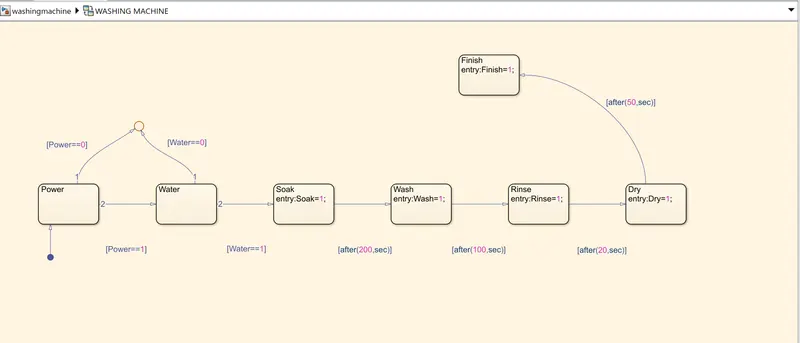
- Create a chart block inorder to define the state flow as per the given conditions.
- Power and Water are defined as the input blocks whereas Soak,Wash,Rinse,Dry and Finish are assigned as the output blocks.
- Inside the chart block,a circular junction is used to terminate the signal flow and return a null value.
- If Power is OFF,that is 0,the process is terminated at the junction,else 1 is carried forward.
- If Water is OFF,that is 0,the process is terminated at the junction,else 1 is carried forward.
- When both Power and Water blocks are ON,that is 1,the Soak block gets activated and soaking action takes place for 200sec.
- After 200sec of soaking,Wash block gets activated and the washing action takes place for 100sec.
- After 100sec of washing,Rinse block gets activated and the rinsing action takes place for 20sec.
- After 20sec of rinsing,Dry block gets activated and the drying action takes place for 50sec.
- After 50sec of drying,Finish block gets activated.Finish terminates the signal flow and exits the chart.
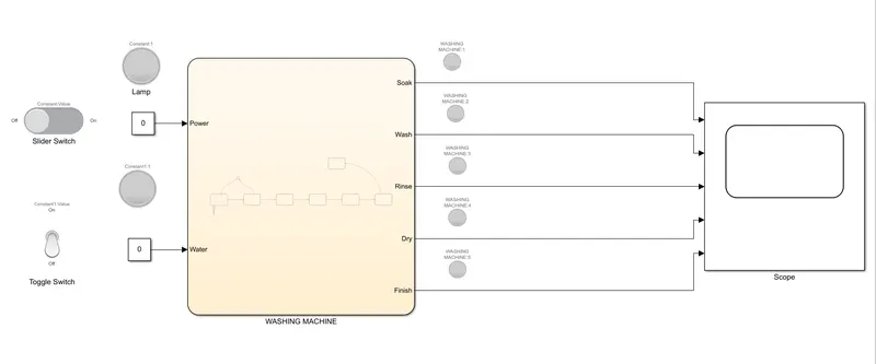
- Connect the chart block with the constants for Power and Water inputs.The slider switch and the toggle switch are connected to them respectively inorder to regulate their switching actions.Lamps are connected to both inputs and outputs inorder to observe their states.
- A common scope is connected to all the outputs inorder to observe and analyze the entire washing process at different intervals of time.
- The blue colour of the lamp in the Finish block indicates the end of the washing cycle.
SIMULINK MODEL OF AN OPERATING WASHING MACHINE:
STATEFLOW:
INPUT 1:
POWER:ON; WATER:OFF
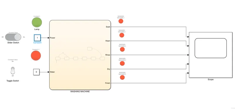
Since Water is OFF, that is 0, the circular junction terminates the entire process and hence none of the processes take place
INPUT 2:
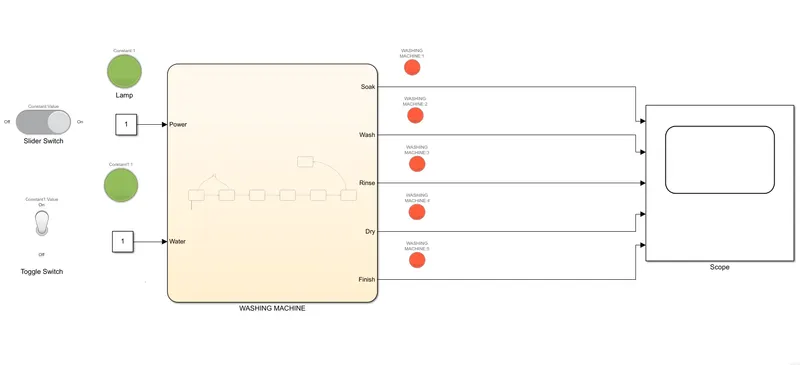
POWER:ON; WATER:ON; TIME=0sec
GRAPH:
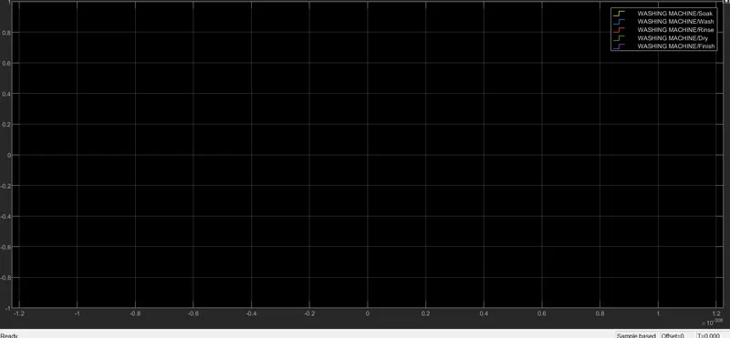
At t=0sec,instantaneously none of the actions take place even though the Power and Water blocks are at logic high inputs
INPUT 3:
POWER:ON; WATER:ON; TIME=10sec
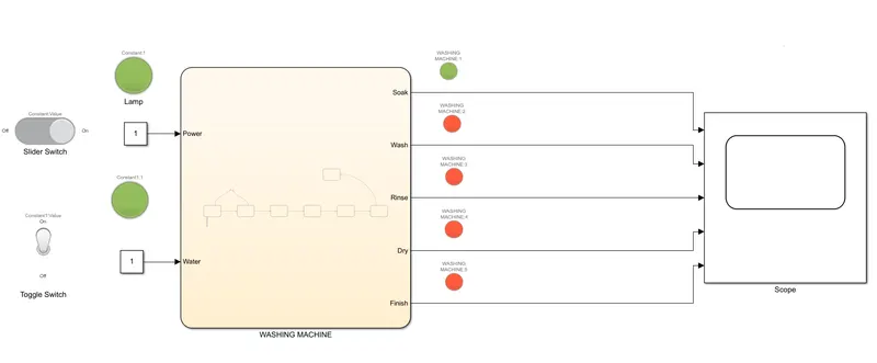
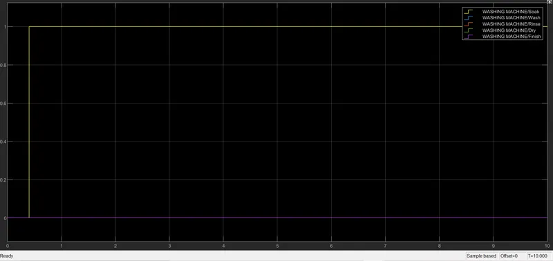
When the simulation time is set to 10sec with both Power and Water in the ON condition,the soak block gets activated and hence we can observe an output of logic 1 in the graph.
INPUT 4:
POWER:ON; WATER:ON; TIME:250sec
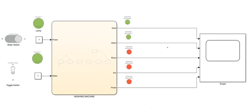
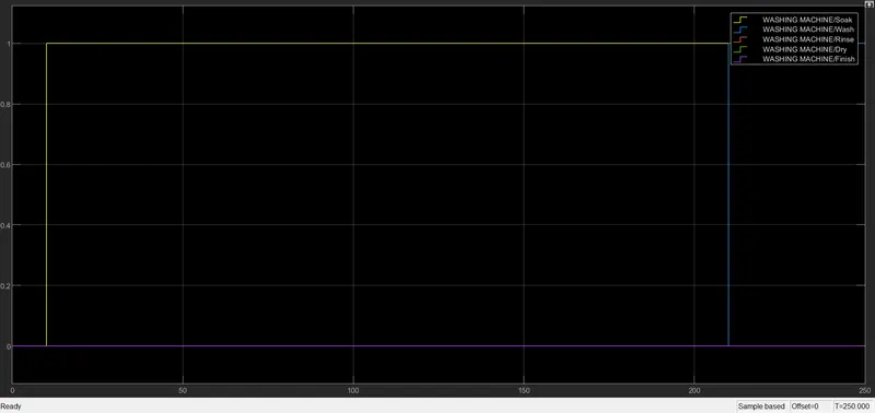
When t=250sec,the Soak block would have completed it's task of soaking for 200sec and the Wash block gets activated after 200th sec.The logic 1 for Wash shows the starting of the washing action.
INPUT 5:
POWER:ON; WATER:ON; TIME=330sec
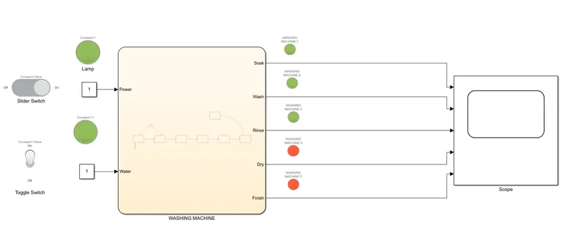
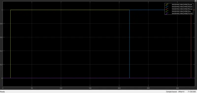
When t=330sec, the washing action takes place for 100sec and hence gets completed at the 300th sec. At 301th sec, the Rinse block gets activated and hence the graph shows a logic 1 ouput
INPUT 6:
POWER:ON; WATER:ON; TIME=360sec
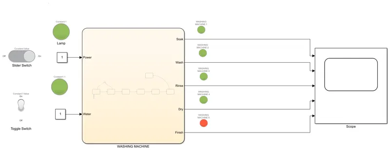
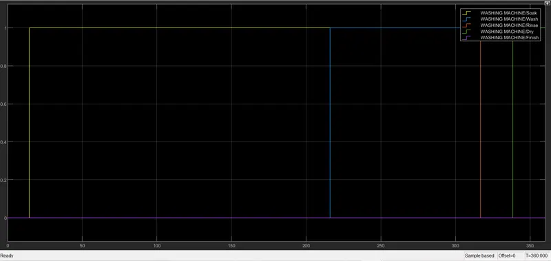
When t=360sec,the rinsing action takes place for 20sec and hence gets completed at the 320th second and after that the Dry block gets activated and hence it shows a logic1 in the output graph.
INPUT 7:
POWER:ON; WATER:ON; TIME=450sec
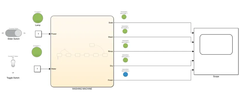
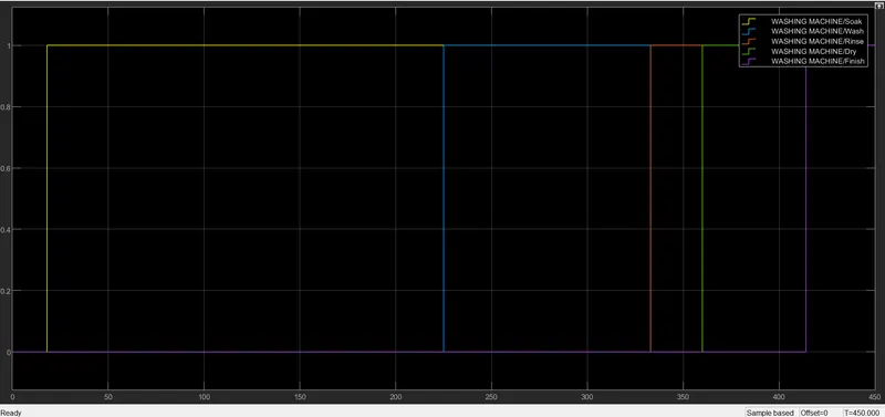
When t=450sec,the drying action takes place for 50sec and gets completed.Once this action is complete,the Finish block is activated and it indicates by a blue clour lamp signalling the end of the process.The output graph shows a logic1 for Finish.
RESULT: The flow chart of the washing machine is built and the various conditions given are tested and their respective output graphs have been plotted.
2)
AIM:To create a Simulink chart for the gear shift logic
OBJECTIVE:To implement a gear shift logic using Simulink as per the below conditions:
Speed range(kmph) Gear
0-15 1
16-25 2
26-40 3
41-60 4
Above 61 5
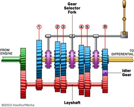
THEORY:A gear is a rotating machine part featuring cut teeth or cogs, which is supposed to mesh with another toothed part in order to transmit torque. Gears are one of the most crucial parts of any motors and machine which help to increase the torque output by providing gear reduction and adjusting the direction of rotation. Two or more gears working together in tandem are called transmission or gearbox. Geared devices are more likely to change the speed, torque, direction of a power source.
A Gear Box is an assembly consisting of various gears, synchronizing sleeves, and a gear-shifting mechanism fitted inside a metal housing.The gearbox is a part of the ‘transmission’ system as the gears play an important role in transmitting the engine power to the wheels.
A gear box contains gears of different sizes. This is mainly because of the vehicle's varying demands in terms of the torque required at the wheels depending upon the road, terrain & load. E.g., if a vehicle is climbing a slope, it needs higher torque than cruising on a straight road.
The first gear is the biggest in size in a gear box and provides maximum torque output while producing minimum speed. Hence, it is used when climbing slopes. All the gears between 1st and last gear vary in size, in a decreasing ratio. Thus, it provides a varying combination in terms of pulling ability and speed. So, the vehicle could be driven smoothly without any drop in its acceleration. The gear box basically improves the vehicle's driveability in all conditions.
PROCEDURE:
- Create a chart block for defining the state flow as per the given conditions.
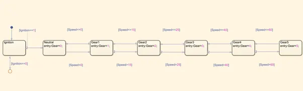
- Inside the chart block,a circular junction is used to terminate the signal flow and return a null value.
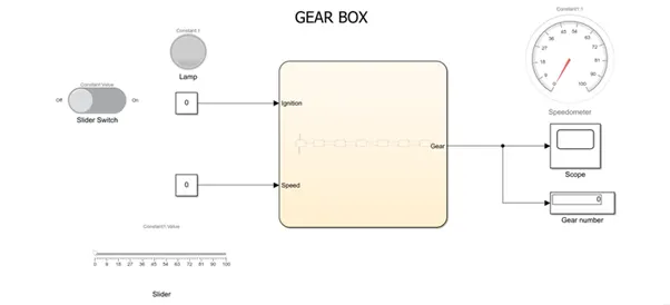
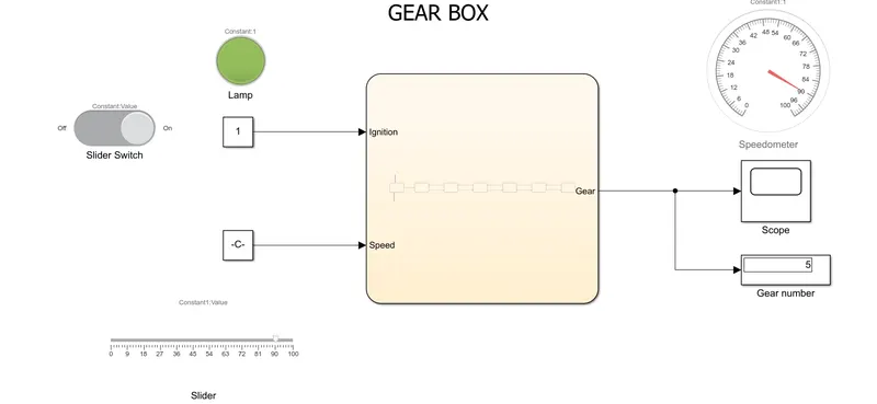
- Ignition and speed are defined as the inputs whereas the Gear, speedometer and the gear number display are the outputs.
- If ignition is OFF, that is 0,the process is terminated at the junction.Else 1 is carried forward.
- If the speed is less than 0,the process is even terminated in this case at the junction.
- If the ignition is ON and the speed is <=0, the neutral gear gets activated.
- If the speed is greater than 0 and less than or equal to 15kmph, Gear 1 is activated.
- If the speed is greater than 15 and less than or equal to 25kmph, Gear 2 is activated.
- If the speed is greater than 25 and less than or equal to 40kmph, Gear 3 is activated.
- If the speed is greater than 40 and less than or equal to 60kmph, Gear 4 is activated.
- For speeds greater than 60kmph, Gear 5 is activated.
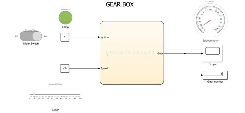
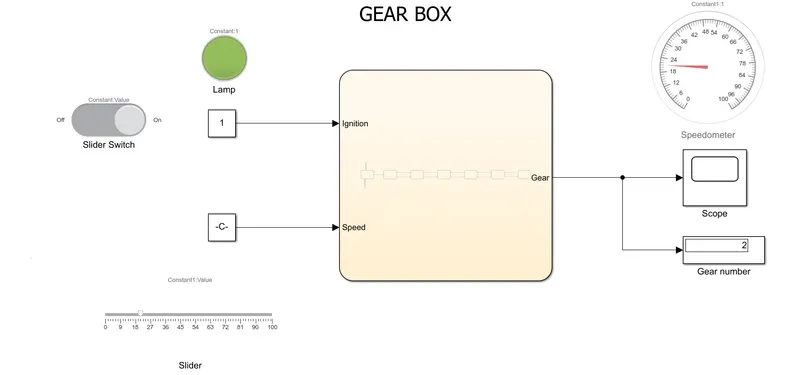
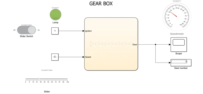
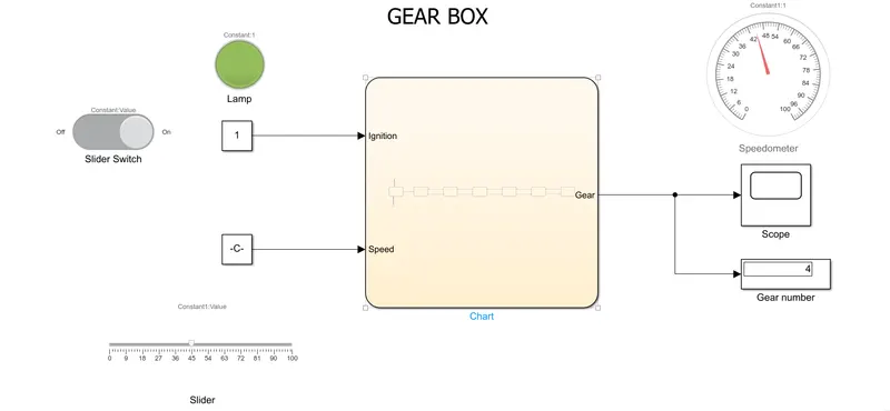
- The chart block is connected to the inputs Speed and Ignition via constant blocks.The slider switch is connected to the constant block which is inturn connected to the input Ignition inorder to switch it on and off. A lamp is connected inorder to monitor this action. The slider bar is connected to the other input,that is speed inorder to adjust variable speed.
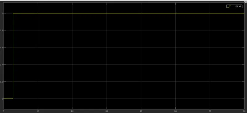
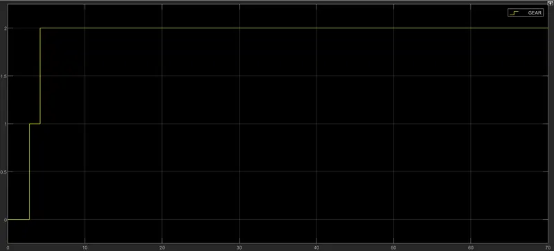
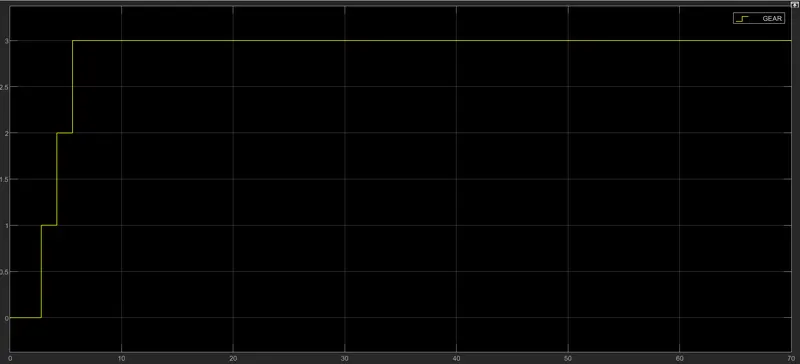
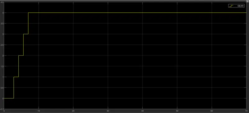
- A common scope block is connected to observe the variation of gears in accordance with the speed. The gear number block displays the gear.
SIMULINK MODEL:
STATE FLOW:
INPUT 1:
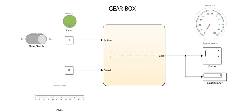
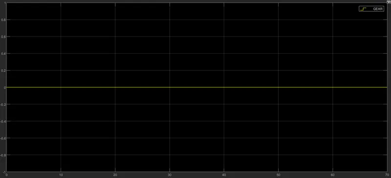
IGNITION:ON; SPEED:0; GEAR:0
INPUT 2:
IGNITION:ON; SPEED:0 TO 15; GEAR:1
INPUT 3:
IGNITION:ON; SPEED:16 TO 25; GEAR:2
INPUT 4:
IGNITION:ON; SPEED:26 TO 40; GEAR:3
INPUT 5:
IGNITION:ON; SPEED:41 TO 60; GEAR:4
INPUT 6:
IGNITION:ON; SPEED:ABOVE 60; GEAR:5
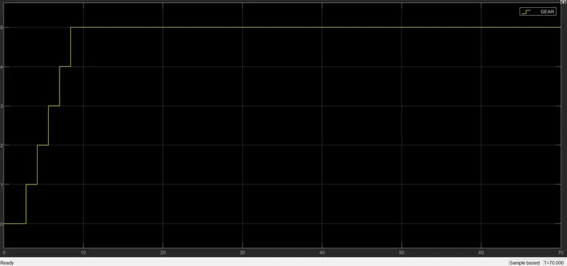
RESULT:The Simulink chart is built as per the given conditions and tested. The output graphs for the respective are displayed above.