Week -2
CHALLENGE 2
1)
AIM: To construct a Simulink model of a doorbell using a solenoid block
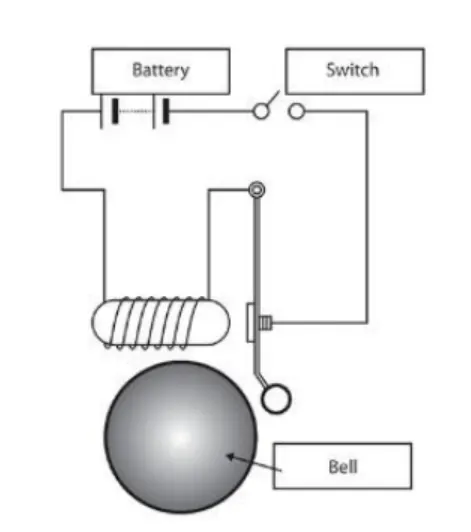
SOLENOID:A solenoid is a device comprised of a coil of wire, the housing and a moveable plunger (armature). When an electrical current is introduced, a magnetic field forms around the coil which draws the plunger in. More simply, a solenoid converts electrical energy into mechanical work.
Solenoids are incredibly versatile and extremely useful. They're found in everything from automated factory equipment to paintball guns and even doorbells. In a chime doorbell, the audible chime is produced when a metal piston strikes a tone bar. The force that moves the piston is the magnetic field of a solenoid that receives electric current when the doorbell is pushed.
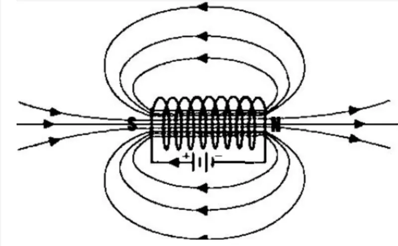
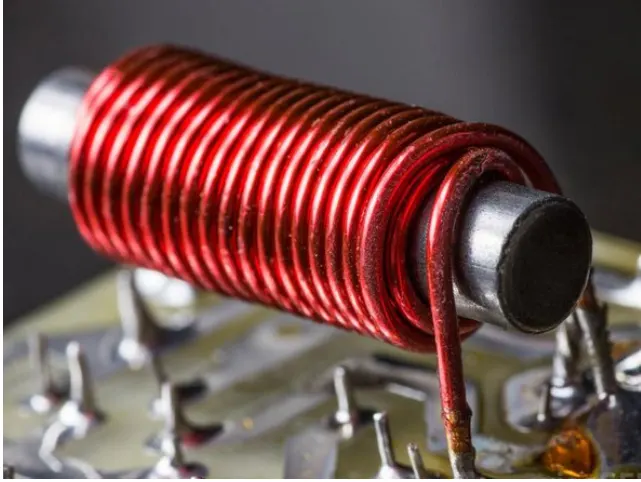
- A chime doorbell uses a specialized sort of electromagnet called a solenoid. A solenoid is just an electromagnet where the coiled wire surrounds a metal piston. The piston contains magnetically conductive metal, so it can be moved backward or forward by the electromagnetic field.
-
In this design, the solenoid piston consists of an iron core mounted to a non-magnetic metal bar. When there is no power to the electromagnet, a spring pushes the piston to the left, and the iron core extends outside of the wire coil. When you turn the electromagnet on (by pressing the doorbell button), the iron core is drawn to the magnetic field, so it slides into the center of the coiled wire.As the iron core slides to the right, the end of the piston strikes the right-hand tone bar. The tone bar vibrates, producing a particular note. This is the "ding" sound.
- As long as you hold the doorbell button, current will flow through the electromagnet and the piston will remain in this position. But when you release the button, the current will stop flowing through the electromagnet and the magnetic field will collapse. The spring snaps the piston back to the left, where it hits the tone bar on the other side. The second tone bar produces the "dong" sound.
SIMULINK MODEL:
BLOCKS USED:
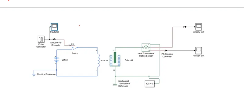
- INPUT(PULSE GENERATOR): The pulse generator block produces square wave at regular intervals.By varying parameters such as amplitude,time period,pulse width and phase delay,we can vary the shape of our input wave.
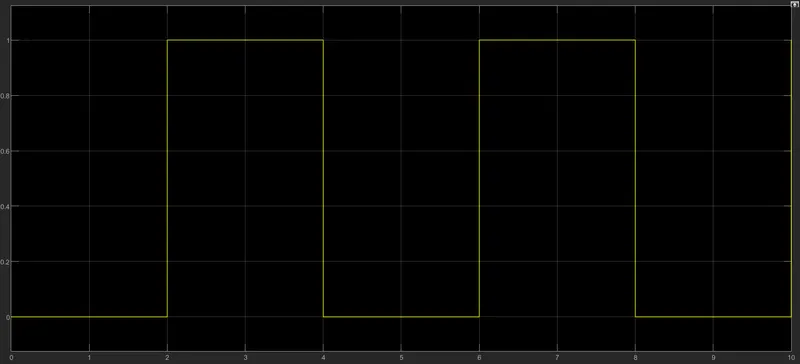
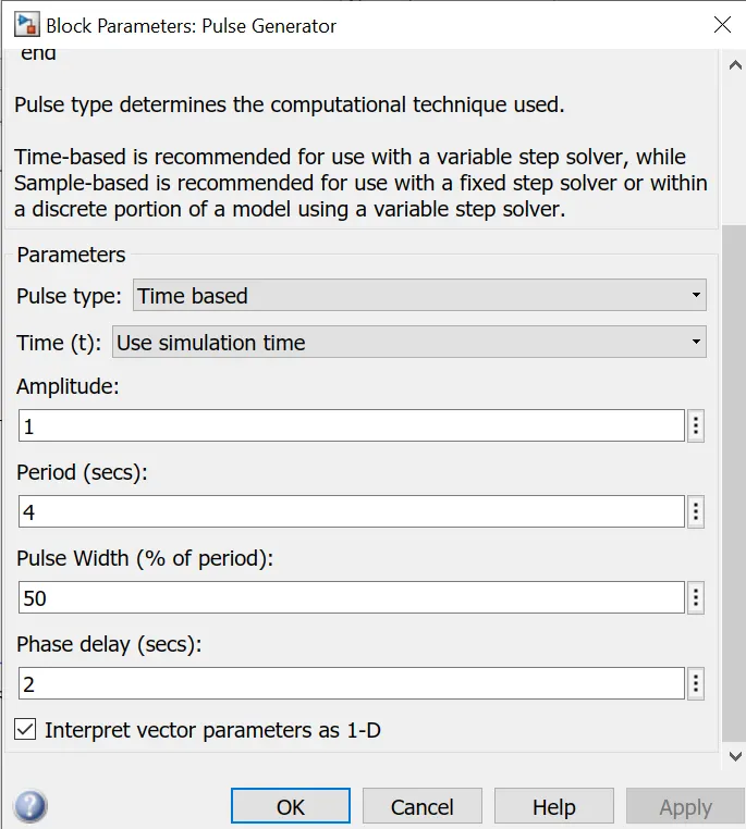
Here the input is provided through the pulse generator.The input has an amplitude of 1 and a time pulse is generated for every 2 seconds and to control the switch in a span of 50s.The pulse is such that it is on for every 2 seconds.
- SIMULINK-PS CONVERTER:This block converts a Simulink input signal into it's corresponding physical state input.
- SWITCH:The switch is controlled by the external physical signal.
- BATTERY:It powers the closed loop.
- ELECTRICAL REFERENCE:It's the electrical grounding connection.
- SOLENOID:This block represents the electrical characteristics and generated force for the solenoid.It converts the electrical characteristics to mechanical.
- IDEAL TRANSLATIONAL MOTION SENSOR:Represents a device that converts an across variable measured between two mechanical translational nodes into a control signal proportional to velocity or position. You can specify the initial position (offset) as a block parameter.The sensor is ideal since it does not account for inertia, friction, delays, energy consumption.
- PS-SIMULINK CONVERTER:It converts the physical state signal to simulink output signal.
- MECHANICAL TRANSLATIONAL REFERENCE:Reference connection for the mechanical parts.
- SCOPE:Displays the waveforms generated during the entire simulation process.
FLOW PROCESS:
- The pulse generator generates signals every 2sec inorder to control the switch to ring the bell.
- The generated signals are converted to real time environment conditions.
- According to the signal,the switch acts to control the flow of current through the solenoid.
- When the current is passed through the solenoid,it generates magnetic field and gets attracted to the iron armature.
- From the solenoid the motion is sensed through the ideal motion sensor.
- The signal is converted back to the Simulink phase inorder to record the motion of the hammer.
OUTPUT WAVEFORMS:
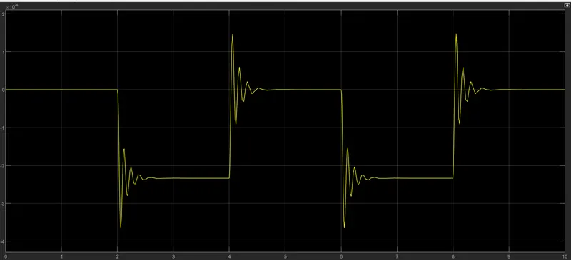
POSITION PLOT:
VELOCITY PLOT:
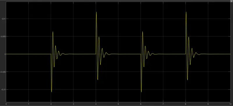
The spikes in the graph are observed during the closing of switch due to magnetic interferences.
RESULT: The simulation runs for 10sec and we can observe from the above graph that the bell rings for every 2sec when the switch is on. During this time the plunger moves to close the air gap.And when the switch is turned off,the plunger moves back to its original position without any oscillation.
2)THERMISTOR CONTROLLED FAN
AIM:To use a thermistor to sense the temperatureof a heater and turn on and turn off the fan as per the below conditions:
Temperature source:20C from 0 to 20 seconds.
27C from 10 to 30 seconds.
23C from 30 to 50 seconds.
Fan conditions:ON if the temperature is above 25C.OFF otherwise.
THERMISTOR:A thermistor is a resistance thermometer, or a resistor whose resistance is dependent on temperature. The term is a combination of “thermal” and “resistor”. It is made of metallic oxides, pressed into a bead, disk, or cylindrical shape and then encapsulated with an impermeable material such as epoxy or glass.Thermistors are available in two types: those with Negative Temperature Coefficients (NTC thermistors) and those with Positive Temperature Coefficients (PTC thermistors). NTC thermistors' resistance decreases as their temperature increases, while PTC thermistors' resistance increases as their temperature increases.Thermistors are used as temperature sensors. They can be found in every day appliances such as fire alarms, ovens and refrigerators. They are also used in digital thermometers and in many automotive applications to measure temperature.
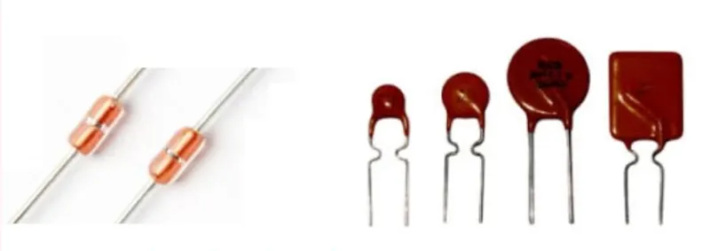
THEORY:Simple Temperature Controlled DC Fan Circuit is designed with Negative temperature co-efficient Thermistor and an operational amplifier. This thermistor has variable resistance value based on the temperature, When the temperature rises, the thermistor resistance decreases and when the temperature decreases, the thermistor resistance increases. We can choose the threshold point of temperature by using variable resistor.
BLOCK DIAGRAM:
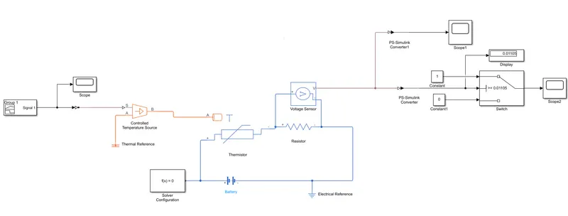
The required signal is built by the signal builder and inputted to the controlled temperature source via Simulink-PS converter. Now the A terminal of the source is connected to the thermal reference. The temperature control source is connected to the thermistor which is in turn is connected to a voltage sensor or a voltmeter. A connection between the thermistor and battery is also established and provided with a solver configuration block. The voltmeter is connected to the middle port of the switch through a PS-Simulink converter. The other two ports of the switch are connected to constants 1 and 0 respectively. The input and output of the ports are connected to a scope. Further all the electrical components are converted to an electrical reference whereas the thermal components are connected to the thermal reference in order to complete the circuit.
INPUT: The input temperatures are provided through a signal builder block. They are in the Kelvin scale
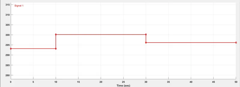
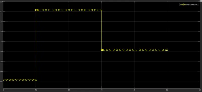
We can observe from the above plots that the temperature is 20C(293.15K) from 0 to 20sec, 27C(300.15K) from 10 to 30sec and 25C(296.15K) from 30 to 50sec. The time period for this simulation is set to 50sec.
WORK FLOW:
- The signal builder block is connected to the Controlled Temperature Source through a Simulink-PS converter
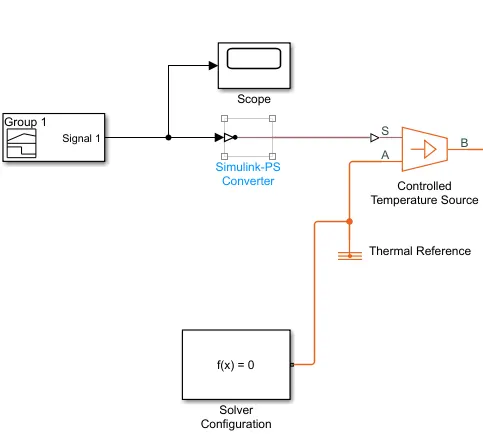
- This temperature source is connected to the thermistor to give resistance in accordance with the temperature.
- A voltmeter or a voltage sensor is connected in parallel to a resistor which is in series with the thermistor to determine the output voltage signal given by the thermistor as it shows the same value due to their series connection.
- A solver configuration and an electrical reference is provided to the circuit.
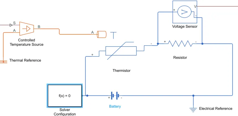
- The output of the voltmeter is connected to the switch inorder to switch and satisfy the conditions.
- Voltage threshold of 25C is found and is given as the input to the switch.
- If the temperature increases the threshold value, it switches to 1.If it is below the threshold value,the switch output is 0.
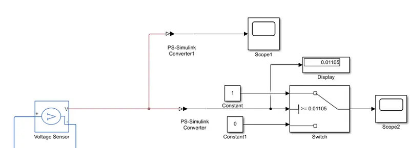
- Electrical references with solver configurations are added .
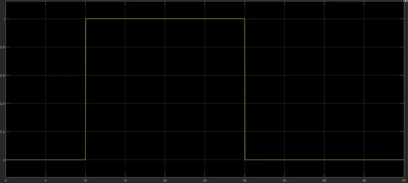
- Motion of the fan based on the temperature conditions is plotted by the scope block.
OUTPUT:
CONCLUSION:
- We can infer from the above graph that only when temperature exceeds 25C,that is 27C from 10sec to 30sec, the fan shows displacement and starts rotating.For temperature 20C from 0sec to 10sec and 23C from 30sec to 50sec,it does not show any displacement.
- Hence the conditions given are satisfied by the usage of a thermistor.