Project
PROJECT
AIM:To study the system level simulation of BAJA All Terrain Vehicle(ATV) using Simulink and thus create a detailed technical report elucidating the model properties and thus commenting on the results.
THEORY:
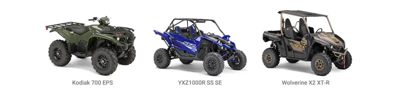
ALL TERRAIN VEHICLE(ATV): An all-terrain vehicle (ATV), also known as a light utility vehicle (LUV), a quad bike, or simply a quad,is a vehicle that travels on low-pressure tires, with a seat that is straddled by the operator, along with handlebars for steering control.The rider sits on and operates these vehicles like a motorcycle, but the extra wheels give more stability at slower speeds. Although most are equipped with three or four wheels, six-wheel models exist for specialized applications.
The applications of these vehicles are:
- Sports
- Entertainment
- Agriculture
- Military & Defense
- Hunting & Forestry
Some of the key players in the all-terrain vehicle market are Polaris Industries (US), Textron (US), Honda (Japan), Kawasaki (Japan), Suzuki (Japan), and BRP (Canada).
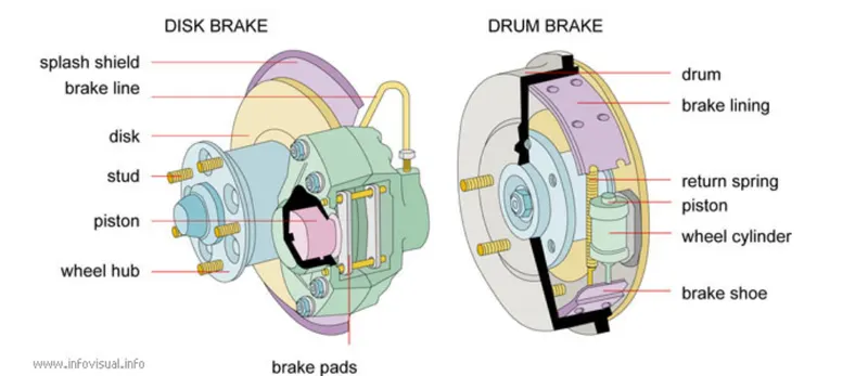
BRAKE:A brake is a mechanical device that inhibits motion by absorbing energy from a moving system. It is used for slowing or stopping a moving vehicle, wheel, axle, or to prevent its motion, most often accomplished by means of friction.
- Hydraulic braking system
- Electromagnetic braking system
- Advantages of Electromagnetic braking system
- Servo braking system
- Mechanical braking system
- Disc Brakes
- Drum Brakes
- Emergency Brakes
- Anti-Lock Brakes
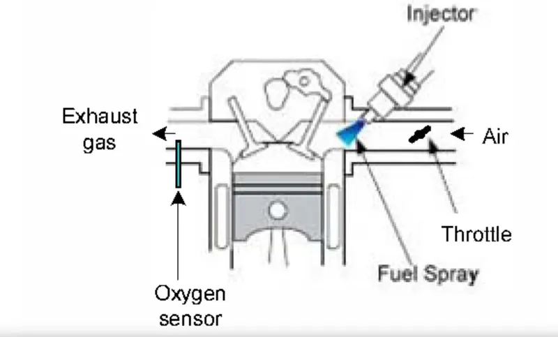
THROTTLE:A throttle is the mechanism by which fluid flow is managed by constriction or obstruction.An engine's power can be increased or decreased by the restriction of inlet gases (by the use of a throttle), but usually decreased. The term throttle has come to refer, informally, to any mechanism by which the power or speed of an engine is regulated.Electronic throttle control facilitates the integration of features such as cruise control, traction control, stability control, and precrash systems and others that require torque management, since the throttle can be moved irrespective of the position of the driver's accelerator pedal.
SIMULINK MODEL FOR BAJA ATV WITH CVT USING DASHBOARD:
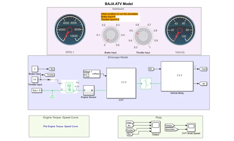
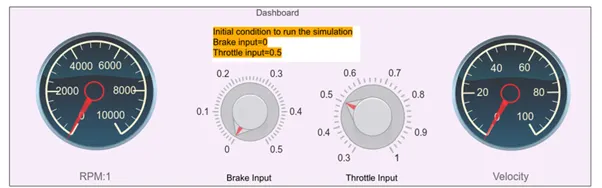
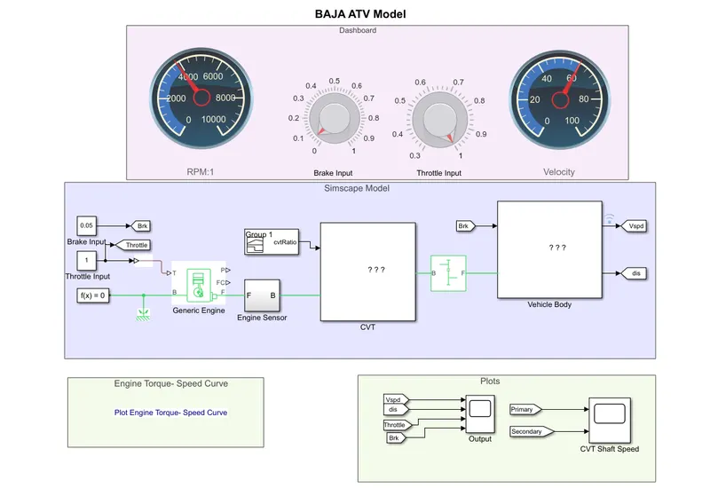
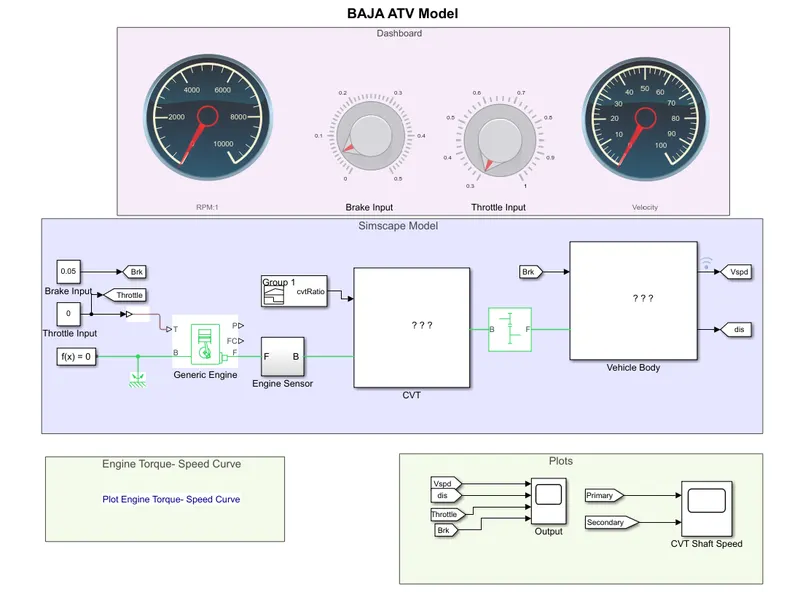
The above figure shows a model of the BAJA ATV with a dashboard in which the inputs brake and throttle are varied using meters in the dashboard instead of using signal builder blocks making it a much more efficient process.The main purpose of using a dashboard is inorder to study the properties of the vehicle speed at various value of input brake and throttle.
BLOCKS USED:
CONTINOUSLY VARIABLE TRANSMISSION(CVT):
A transmission is a machine in a power transmission system, which provides controlled application of power. Often the term 5-speed transmission refers simply to the gearbox, that uses gears and gear trains to provide speed and torque conversions from a rotating power source to another device.Vehicles need a transmission to transfer the power from the engine to the drive shaft and the differential to let the wheels turn. The transmission varies the torque, the speed and the direction by changing the transmission ratios and enables the car to start with a high torque.
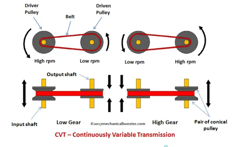
A continuously variable transmission (CVT) is an automatic transmission that can change seamlessly through a continuous range of gear ratios. This contrasts with other transmissions that provide a limited number of gear ratios in fixed steps. The flexibility of a CVT with suitable control may allow the engine to operate at a constant RPM while the vehicle moves at varying speeds
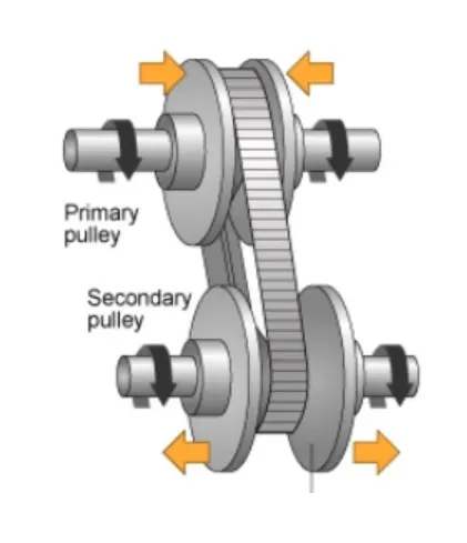
Unlike a conventional automatic transmission system, the CVT does not make use of gears. Instead, it has two pulleys, whose diameters are variable and are connected by a belt or a chain. One end is connected to the engine and the other one is linked to the wheels, where the power is delivered.
Advantages of CVT:
- Outstanding fuel efficiency is a major advantage for your Bloomfield and Troy commutes. CVTs are always adjusting, so they keep engine RPMs low and consistent, avoiding the high engine speeds that suck down gasoline.
- CVTs also have lower production costs because they have fewer moving parts than traditional automatics. This is another appealing factor to car manufacturers, and thus to car buyers as well.
- CVTs deliver a smooth ride because the transmission doesn’t have to constantly switch gears.
CVT SUBSYSTEM:
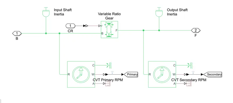
The subsystem of a CVT consists of the Input Shaft Inertia and the Output Shaft Inertia which represent the primary and secondary pulleys respectively.Inorder to specify the gear ratio,the Variable Gear Ratio block has been provided.The physical signal input 'r' defines the ratio of input to output angular shaft velocities. The Ideal Rotational Motion Sensor provides us the primary and secondary rpm.
VEHICLE BODY:
VEHICLE BODY SUBSYTEM:
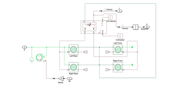
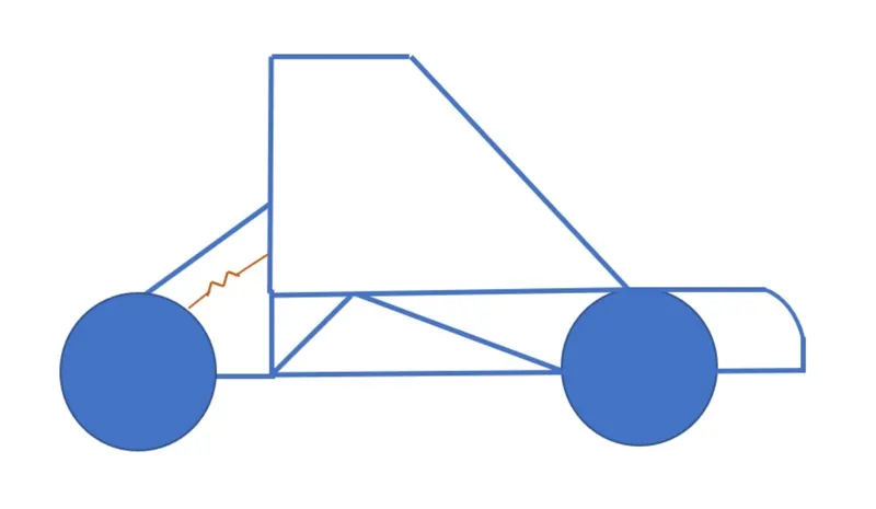
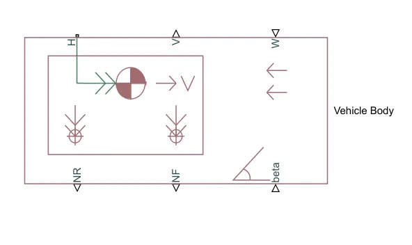
The Vehicle Body block represents a two-axle vehicle body in longitudinal motion. The vehicle can have the same or a different number of wheels on each axle. For example, two wheels on the front axle and one wheel on the rear axle. The vehicle wheels are assumed identical in size. The vehicle can also have a center of gravity (CG) that is at or below the plane of travel.
The block accounts for body mass, aerodynamic drag, road incline, and weight distribution between axles due to acceleration and road profile. Optionally include pitch and suspension dynamics. The vehicle does not move vertically relative to the ground.
The block has an option to include an externally-defined mass and an externally-defined inertia. The mass, inertia, and center of gravity of the vehicle body can vary over the course of simulation in response to system changes.
PORTS:
INPUT:
- W-Headwind speed(m/s)
- Beta-Road incline angle(rad)
- CG-Centre of gravity(m)
- M-Mass(kg)
- J-External moment of inertia(kg*m^2)
OUTPUT:
- V-Longitudnal velocity(m/s)
- NF-Front axle normal force(N)
- NR-Rear axle normal force(N)
ENGINE:
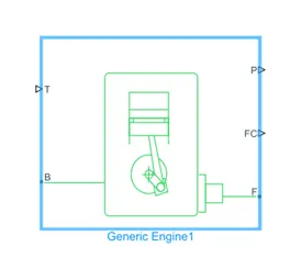
Represents a system level model of a spark ignition or a diesel engine suitable for use only at initial stages of modelling only when the basic parameters are available.Throttle input signal T lies between 0 and 1 and specifies the torque demanded from the engine as a fraction of the maximum possible torque.
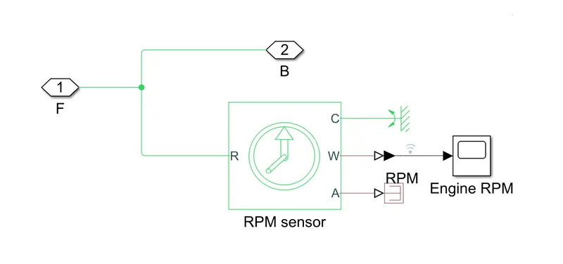
Connections F and B are mechanical rotational conserving ports linked with the engine crankshaft and engine block respectively.Connection P and FC are physical signal output ports through which engine power and fuel consumption rates are tabulated.
ENGINE SENSOR:
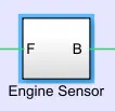
Engine sensors are the electro-mechanical devices which monitor various engine parameters. An engine uses different types of sensors that include are Thermo-couples, Resistance Temperature Detectors (RTDs), and Hall Effect sensors. the engine sensors provide the Engine Management System with vital data parameters in real-time. These engine sensors continuously monitor the engine parameters. They also provide the ECU with changes that occur in the data from time to time. Based on these inputs, the ECU re-calculates the correct air-fuel ratio and ignition timing. It also calculates and supplies the correct amount of fuel to the engine under various load conditions.
INPUT PARAMETERS:
- The input parameters that is the brake input and the throttle input are provided using the dashboard consisting of meters indicating the changes in their input values.
- CVT RATIO:The CVT ratio is provided using the Signal Builder block and this is kept constant throughout the simulation for various conditions of break and throttle inputs.
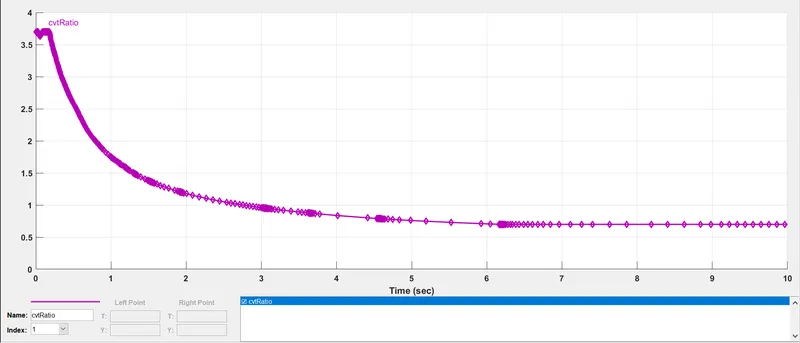
Ratio range is defined as the numerical ratio of the maximum to the minimum output speeds possible for a given fixed input speed. For example, if a CVT can be controlled to operate between 3000 and 1000 rpm for a given fixed input speed, its ratio range is 3.0.The cones can move to increase or decrease the belt diameter to change gear ratios, allow for quick shifting into the needed ratio for increased power, and boost fuel economy. One pulley in the CVT is connected to the engine and the other directs power to the wheels.
- ENGINE TORQUE-SPEED CURVE:
The torque speed curve of a load is a plot showing its torque requirement on the y- axis versus the speed on x-axis. It's the torque requirement of the load from zero speed to full speed. Its application/load specific and varies with different load types.
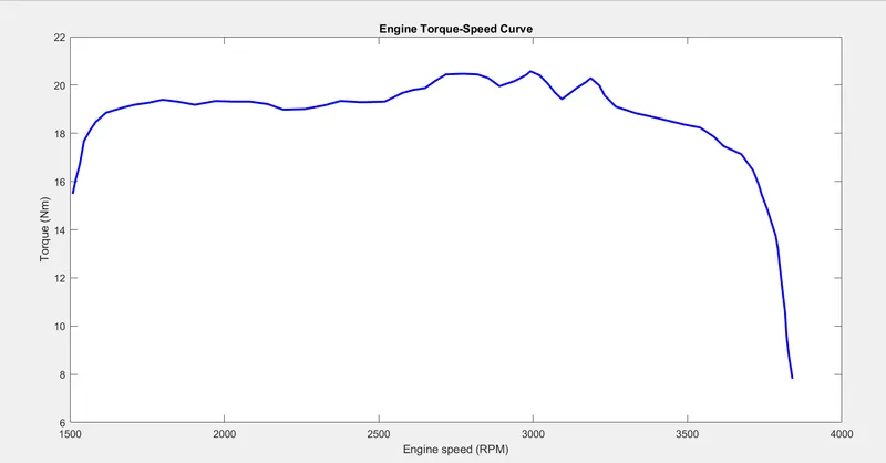
We know that as the gear ratio increases the torque increases which inturn reduces the speed of the vehicle.In the above figure, we can observe that the torque is increasing with increase in the engine speed.After a particular point,the torque goes on reducing as the gear ratio increases inorder to achieve maximum velocity.
CASE STUDY:
CASE 1: BRAKE=0; THROTTLE=0.5
OUTPUT:
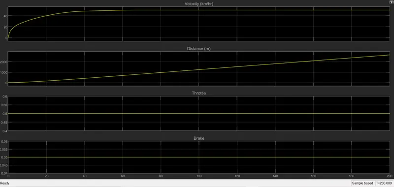
From the above graph,we can observe that the velocity or the speed of the vehicle slowly starts increasing and reaches a maximum velocity of 50km/hr at half throttle=0.5 which is kept contant throughout this simulation.Since the break applied is 0,it has no affect on the velocity.
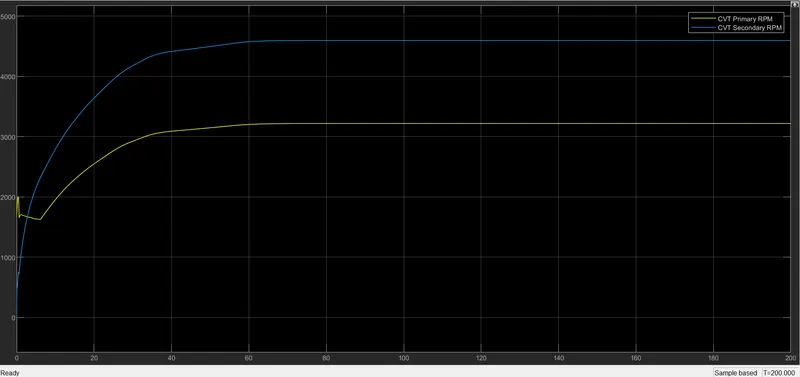
From the above graph we can observe that the primary RPM starts increasing after around 7sec upto 60sec and then attains a constant value of around 3200rpm wheareas the secondary RPM increases upto 60sec and beyond that holds a contant value of around 4500rpm.
CASE 2: BRAKE=0.05; THROTTLE:1
OUTPUT:
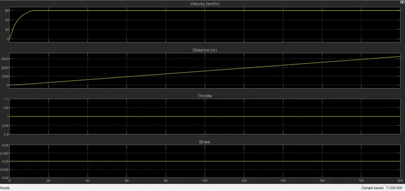
From the above graph, we can observe that the velocity of the vehicle starts increasing and reaches a peak value of 60km/hr and maintains that throughout the simulation at full throttle=1.Since a brake of 0.05 is applied, it affects the vehicle by slowing down.
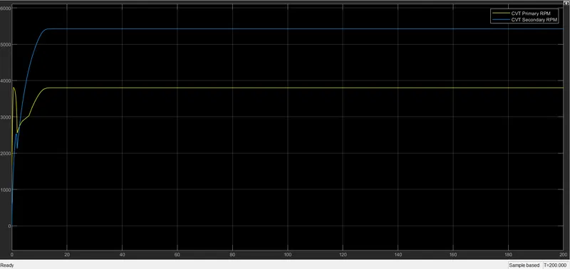
From the above graph we can observe that the primary RPM shows high and low variations upto 15sec and beyond that attains a constant value of around 3750rpm whereas the secondary RPM shows minute variations upto 15sec and beyond that maintains a constant speed of arounf 5950rpm.
CASE 3: BRAKE=0.05;THROTTLE=0
OUTPUT:
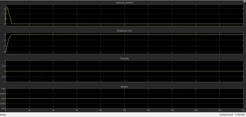
From the above graph we can observe that the speed of the vehicle does not increase much and reduces to zero as the throttle=0,which means that there's no inlet of gases and hence the vehicle doesn't start.The brake applied here is 0.05 which doesn't affect the vehicle as no throttle is applied.
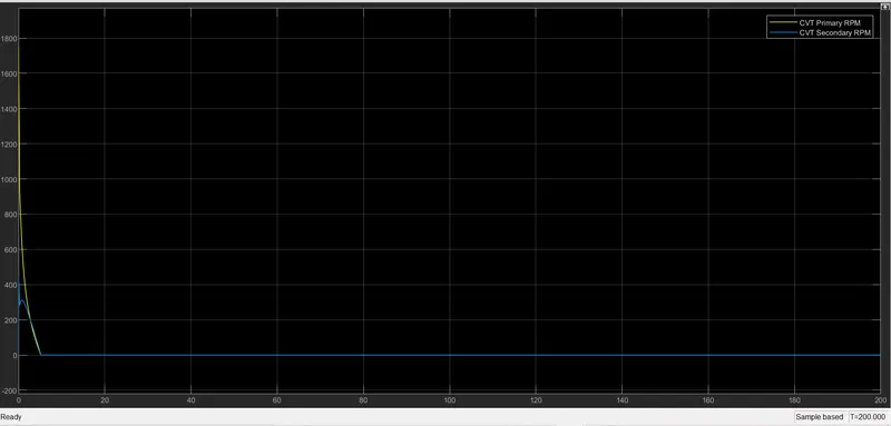
from the above graph we can observe that both primary and secondary RPM reduce exponentially within 5sec and the speed remains 0 throughout the simulation as no throttle is applied to the vehicle.
CONCLUSION: The system level simulation of BAJA All Terrain Vehicle was conducted and the behaviour of the vehicle for various values of brake and throttle were tested and observed successfully and thus a technical report was created.