Week - 4
AIM: To Implement control logic of “washing machine” using stateflow and to make a Simulink chart for the“Gear Shift” logic.
THEORY:
StateFlow - StateFlow provide the graphical language that includes state transition diagram ,flow chart,state transition table & truth tables. it is used to decribe how MATLAB algorithms and Simulink model react to input signals, events and tame based condition.State flow allows you to design and develop supervisory control, task, scheduling, fault management, communication protocols, user interface & hybrid system. With StateFlow, you model combinatorial & seuential decision logic that can be simulated as a block within a Simulink model or executed as an object in MATLAB. Graphical animation enable you to analyse and Debug your logic while executing. edit time and run time check & ensure design consistency and completeness before implemenation.
Control Logic - Control logic is the key part of a Software program that control the operation of program. the control logic repond to the commands from the user & it also acts on its own to perform automated Task that have been structured in program. Controlled Logic can be modelled using a state diagram, which is a form of hierarchical state machine.
OBJECTIVE: I.
- Implement control logic of a “Washing Machine” using Stateflow as per given Sequence:
- If the power supply is available, the system get a active
- If the water supply is not available, stop the process and indicate through LED
- Soaking time should be 200s followed by washing time of 100s.
- Then rinsing happens for next 20s & dryer runs for 50s.
II. After all the processes have completed turn on the finished LED
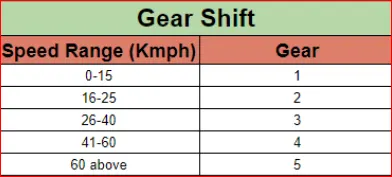
Make a Simulink chart for the “Gear Shift” logic as per below conditions:
Speed Range (kmph) Gear
0 to 15 1
16 to 25 2
26 to 40 3
41 to 60 4
Above 60 5
Give the speed input while simulation is running & display the gear number.
STUDY I - GENERATE A SIMULINK MODEL TO WASHING MACHINE AT VARIOUS STATES.
BLOCKs USED:
1. Constant Block- For Power and Water supply.
2. Switch Block - to determine output.

3. Lamp Block- to indicate the running Signal.

4. Chart Block- to create control logic program.
OPERATIONS PERFORMED:
1. Soaking - 200,sec (0-200 sec).
2. Washing - 100,sec (200-300 sec).
3. Rinsing - 20 sec (300-320 sec).
4. Drying - 50 sec (320-370 sec).
5.Power OFF - After Drying (>370 sec).
WASHING MACHINE:
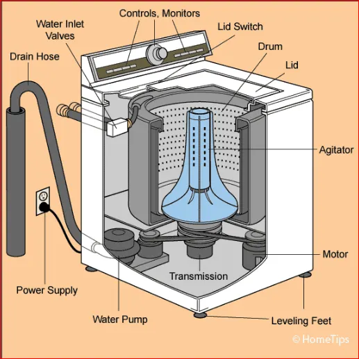
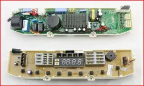
A Washing machine (laundry machine, cloth washer, or washer) is a home appliance used to wash laundry. The term is mostly applied to machine that use water as opposed to dry cleaning or ultrasonic cleaners. The user adds laundry detergent, which is solid in liquid or powder form, to the wash water.
Washing machine are generally of 2 categories as follows -
1. Semi-Automatic washing machine -
the Semi-Automatic is needed for your assistance to get th job done & you will have to pour the water manually and need to set up the timer.
2.Fully-Automatic washing machine -
The Fully Automatic machine are more convenient & offer a great range of functionality. we get fully automatic functions that carry out the washing without any manual interference. They are little bit budget friendly.
SIMULINK MODEL :-
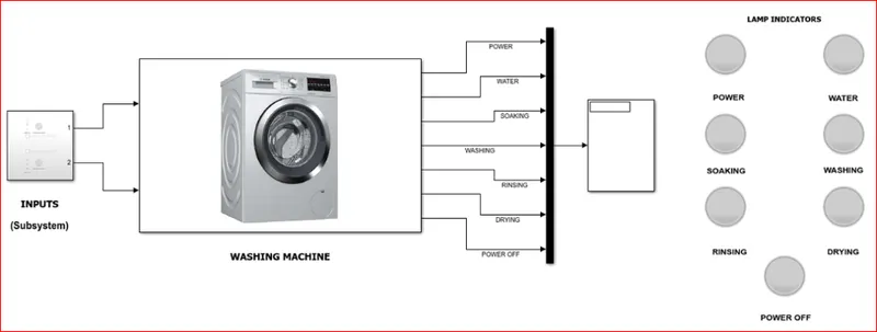
MAIN SYSTEM,
SUBSYTEM,
STATEFLOW MODEL,
EXPLANATION:
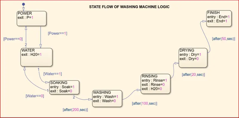
- First, we have created a chart using “CHART BLOCK” to define the logic of the washing machine.
- The First state is “Power” state; this is where the program checks weather the power is ON/OFF. If the Power is ON the process will go to next state or else it will not go further. Here we have defined the variable “P” as it will help us to indicate whether this particular state is going ON or OFF.(in our case we have gave the equation as { exit P = 1} means if the ON{1} Power will pass on to next state & if P = 0 the power is OFF and it will not pass on to next state.)
- Next we have “Water” state; where water will be filled, and similar to that of power state we have defined variable “W” which will help us to see whether is being filled or not. The process between “” and “” is defined as if power is equal to 1 which means if power is ON then only it water state will start , and power equal to 0 is refer as power OFF then it will remain the power state only.
- Now next state is “Soak State”, this is where the cloths are Soaked once the water is filled. Here we have defined inside this state that when it enter the state the value of variable “S” will be 1 which means that this state is going ON. Once this state is over the process exit by value ”S = 0” which means now the state is not going On.
- Now next is the “Wash State” this is where the cloth are washed, here as per conditions mentioned above after 200s of soaking the washing state takes place. This condition is mention between “Soak State” and “Wash State”.
- Then, “Risen State” take place where all the water is drained out, here when the state is in this state it will indicate “R=1” once this state is over it will indicate “R=0” and it will move next state. Process between “Wash State” & “Rinse State” id defined as per the condition mentioned above.
- Next state is the “Dry State” where the clothes are dried inside the machine. Similar condition is defined in the state as like previous states, and the process is defined as per the conditions given the objectives.
- The final state is “Finish State”, this where the process ends and the power needs to be switched off manually. Here also similar condition is mention.
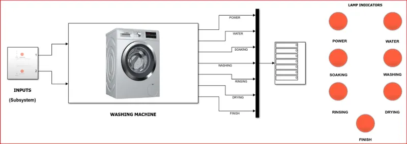
- Now once the Machine Logic is created we have defined the variable entered as output variable and power and water as inputs as these has to be provided to the machine in real time.
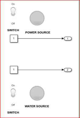
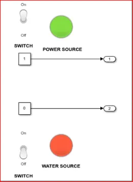
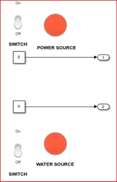
- To give power and water as input we have use “Slider Switch Block” and “Constant Block” is used. Each Slider switch is connected to the chart block where the washing machine program is defined.
- If the slider switch is OFF the value in constant block is “0”which indicate there is no water supply or power supply. By this way we have defined the inputs. And for the outputs we have connected each one with each “Display Block”.
- These display block are then connected to “Lamp Block” which will turn Green when particular state is going and it will be red if that particular state is not going on.
- To set conditions for lamp block, double click on it set the condition as shown, click on the connection on which you want your Lamp to lit.
- Now if u run the model we will see Lamp turning into Green and Red when the particular state is going ON and OFF.
CONDITION I - BOTH WATER AND POWER SUPPLY:-
In this process both power and water supply are provided.
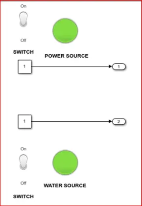
As both the supply are provided so the system gets activated.
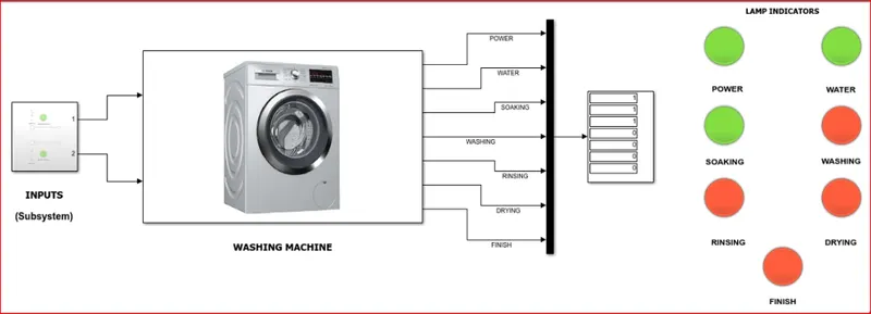
SOAKING STATE,
As the system gets activated tha soaking process starts which is been continued till 200 sec.
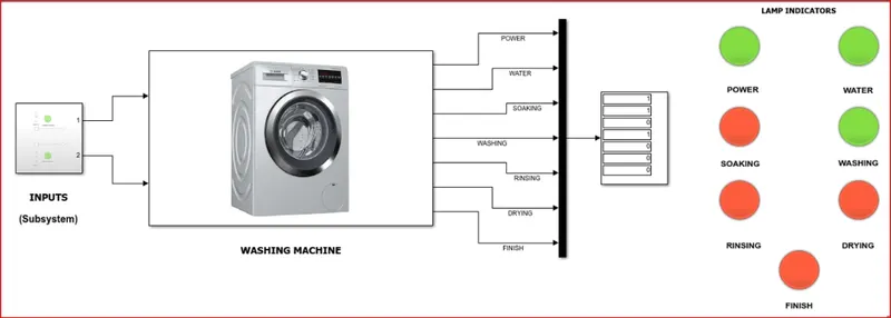
WASHING STATE,
After 200 sec the washing process get initiated which is being continued till 300 sec.
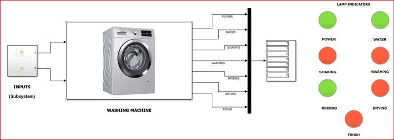
RINSING STATE,
After 300 sec the rinsing process get initiated which is being contined till 320 sec.
DRYING STATE,
After 320 sec the drying process get initiated which is being continued till 370 sec. And once the rinsing stage is crossed the water supply is cut off because for drying it's not required.
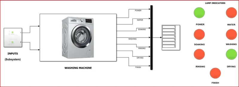
FINISH STATE,
After all the process are completed the washing machine will not take any more water or power to wash the cloths until the user unload the wsshed cloths and load the cloths to be washed. so the finish lamp indicate that the washing cycle is complete.
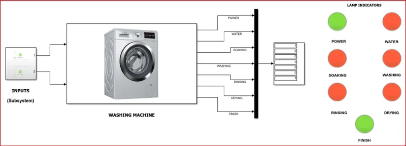
RESULTS :-
The machine ran successfully by completeing all the process so that the cloths are ready to drying under sun.
CONDITION II - NO WATER SUPPLY :-
In this process only power supply is provided and the water supply is turned OFF.
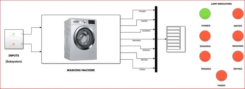
As the water supply is turned OFF the washing machine didn't start the process cycle. only the power supply lamp is blinking.
CONDITION III - NO POWER AND WATER SUPPLY :-
In this process bothe water and power supply is turned OFF.
STUDY II -GENERATE A SIMULINK MODEL TO SHIFT THE GEAR ACCORDING TO INPUT SPEED.
CAR GEAR SHIFTS:
A manual transmission (also known as a manual gear box; abbreviated as MT ) is a multi-speed transmission where gear change require the drive to select the gear by manually operating a gear stick and clutch (which is usually a foot pedal for car, or a hand lever for motorcycles).
Early automobile used sliding mesh manual transmission with up to three forward gear ratios. Since the 1950s, constant mesh manual transmission have become increasingly common place and the number of forward ration has increased to 5- speed and 6-speed manual transmission for current vehicles.
The alternative to a manual transmission is the automatic transmission; common type of transmission is the hydraulic automatic transmission (AT), automated manual transmission (AMT), dual –clutch transmission (DCT), and the continuously variable transmission (CVT).
Gear box is the 2nd element in the powertrain in ana automobile. It is use to change speed and torque of the vehicle accordingly to varity of road and load conditions. The transmission box changes the engine speed into torque when climbing heels as per requirement of the vehicle & hence it is also known as Torque converter.
Following are main function of the Gearbox:-
1. Provide the torque needed to move the vehicle under the vanety of road and load conditions and doing this by changing the gear ratio between Engine Crankshaft and Vehicle Drive wheel.
2. To Provide assistance to shift backward/reverse so that the vehicle moves in that direction.
3. To Help the vehicle to shift into neutral for starting the engine.
Working:-
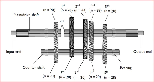
In the gear box the tertiary counter shaft is mashed to clutch with the use of couple of gear so the counter shift is always in running condition. When the tertiary shaft is brought into contact with the main shaft by the mean of meashing gear the main shaft starts to rotate according to the gear ratio. When the Driver wants to change the gear he simply press the clutch pedal which disconnect the teritary shaft with the engine and connect tha main shaft with tertiary shaft by another gear ratio by the use of gear shift lever.
STEPWISE PROCEDURE :-
- Create a Chart box for defining the stateflow as per the given condition.
- If the speed is less than 0 or equals to 0 , the flow is Terminated and Gear 0 is Activated.at the Junction else 1 is carry forwarded.
- If the speed is greater than 0 and less than or equal to 15 , the flow isnactivated and Gear 1 is Activated.
- If the speed is greater than 15 and less than or equal to 25 , the flow isnactivated and Gear 1 is Activated.
- If the speed is greater than 25 and less than or equal to 40 , the flow isnactivated and Gear 1 is Activated.
- If the speed is greater than 40 and less than or equal to 60 , the flow isnactivated and Gear 1 is Activated.
- If the speed is greater than 60, the flow is terminated and Gear 5 is Activated.
CONTROL LOGIC STRUCTURE -
EXPLANATION:
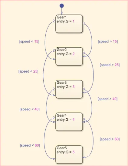
- Here we have used “CHART BOX” to define the gear shift logic for the condition given above as per in objective.
- 1st we have define 5 states namely “Gear_1” “Gear_2” “Gear_3” “Gear_4” “Gear_5”. The
- Now to shift from one state to another we have defined the conditions of the speeds as mentioned above.
- We have also defined the value inside the state which represent that when the particular state is going ON it will display the value that is defined in it. This will help us to see that which gear is operating at particular speed.
- The Transition condition for gear shifty is decided as
Forward direction,
Speed > 15 Shift to G = 2
Speed > 25 Shift to G = 3
Speed > 40 Shift to G = 4
Speed > 60 Shift to G = 5 (When the speed is increasing from 0-60 kmph)
Similarly in reverse direction,
Speed < 60 Shift to G = 4
Speed < 40 Shift to G = 3
Speed < 25 Shift to G = 2
Speed < 15 Shift to G = 1 (When the speed is decreasing from 60-0 kmph)
Symbol panel -
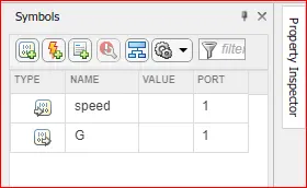
Here, "Speed" is an Input condition and "G" is Output Condition.
FLOWCHART :-
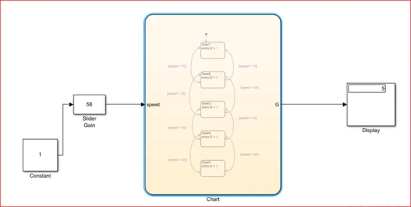
- After event creation flow chart is generated using some blocks from the library and there connection are done as mention below.
- A constant Block is connected with slider gain block to provide initial input.
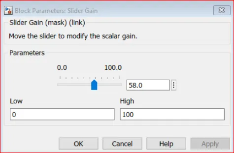
- Slider Gain Block is use to define the speed by sliding the guage as per desire to change the speed during simulation is running and it acts as input for speed.
- the output port (G) is connected with the display to indicate the current engaged Gear for current speed in the slider gain.
RESULTS -
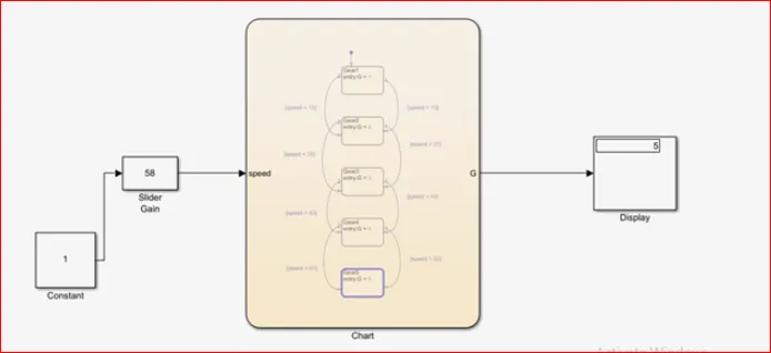
When the run time is kept as an infinite and the slider is made to slide for the speed then we can see the gear number (G) as 4, By changing the slider position the display alue will change simultaneously.
CONCLUSIONS:
- Thus, all objectives were achieved successfully.
- Similar concepts and approach can be adopt to create state flow for other systems