Week - 4
Aim:
- To implement control logic of a washing machine using State flow.
- To make a Simulink chart for the “Gear shift” logic as per given conditions
Conditions:
- Washing machine:
- If power supply is available, the system gets activated
- If water supply is not available, stop the process and indicate through LED
- Soaking time should be 200s followed by washing time of 100s.
- Then rinsing happens for next 20s and dryer runs for 50s
- After all the process are completed turn on the finish LED.
- Gear shift:
- For speed range of 0 to 15, gear 1
- For speed range of 16 to 25, gear 1
- For speed range of 26 to 40, gear 1
- For speed range of 41 to 60, gear 1
- For speed range of above 61, gear 6
Give the speed input while the simulation is running & display the gear no.
Explanation:
1: washing machine:
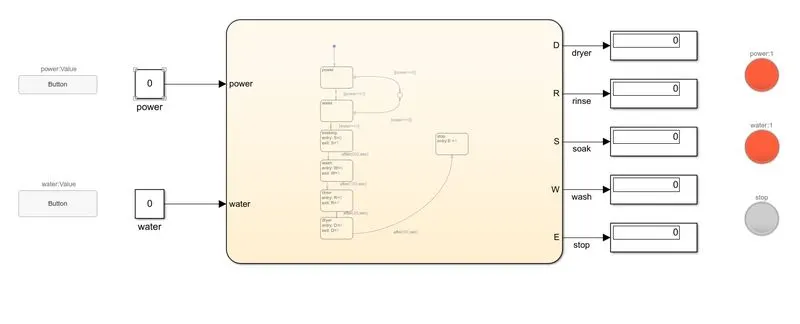
- the blocks used in this model are constant, push button, display, lamp, junction, state, etc.
- The constant blocks are used to give the input of power and water supply which are connected to the buttons.
- These water and power supplies are considered as inputs to the system and to the chart and state blocks are used inside the charts and directed by transitions.
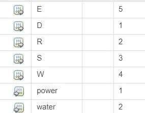
- If power, water is in power==0, water==0, it moves directly to the junction and if power==1 or water==1 it moves to the next state.
- Next to water it goes to the soaking state where the entry is given as 0 and exit with 1, after 200s it is then connected to the washing state.
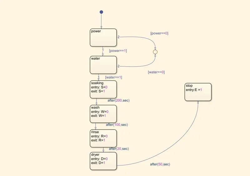
- Washing takes 100sec and then directed to rinsing which will be 20sec later to the dryer for 50sec and to the end sate.
2: Gear shift:
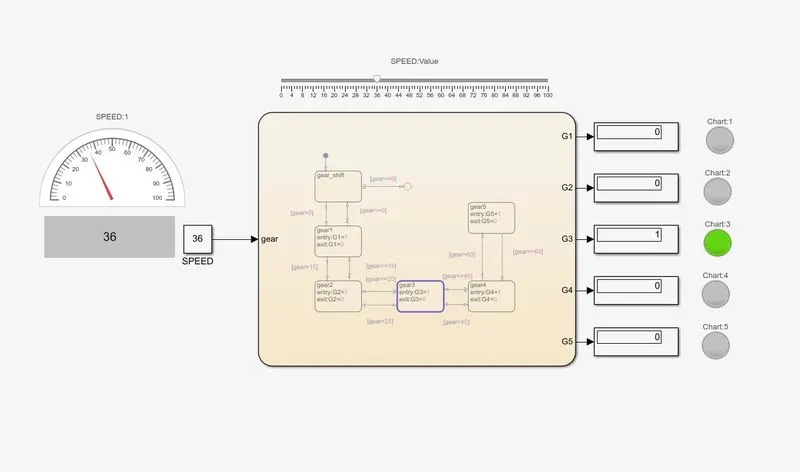
- The blocks used in this are constant, half gauge, slider, lamp, display and in chart are state, junction and transitions.
- As per given instructions that the speed has to be changed alternatively during the simulation, the simulation time has been set to inf(infinite).
- The constant block is set to manage the value of speed as input, slider block is connected to the constant block.
- With the help of the slider, we can alter the value of speed and a half gauge is connected to the constant for indication of speed.
- In the chart, in the first state it is mentioned as gear shift with conditions gear>0 it goes to the next state and if gear==0 it stays in that state.
- Similarly, for the further states if gear>previous speed (0,1,25,40,60) it goes to the higher state(gear) and if gear<= (15,25,40,60) it goes to previous state.
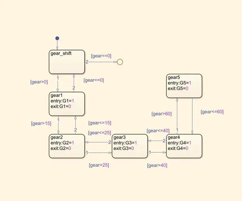
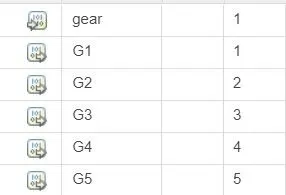
- The gears G1, G2, G3, G4, G5 are given as output parameters in property inspector.
- During the simulation the lamps with respective gear glow to indicate the gear.
Results:
1:after the whole procedure if wasing process.
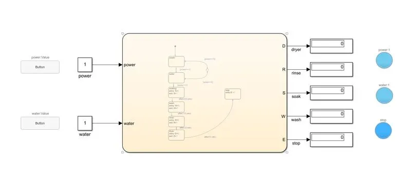
2: gear shift to gear (G3) during the speed of 36.