2D Meshing of a plastic Bottle cap by extracting manual midsurface using ANSA
2D MESHING OF A PLASTIC BOTTLE CAP BY EXTRACTING MANUAL MIDSURFACE USING ANSA
AIM:
- To Extract the mid surface manually for the given bottle cap and to mesh the same with 2d shell elements by maintaining the below said quality criterions.
- To assign the thickness for the meshed bottle cap.
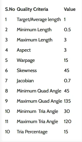
Fig:Quality Criteria.
PROCEDURE:
1. Open the given Bottle cap model in ANSA.
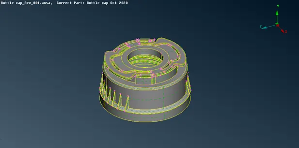
Fig: Imported model of Bottle cap.
2. Check for the geometry errors by running geometry checks. Fix the issues if any found any.
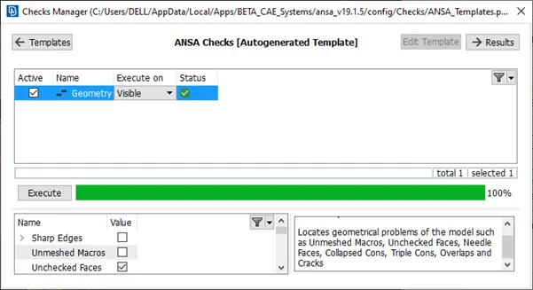
Fig: Geometry check.
3. Measure the thickness of the component at different locations using measure tool and store the dimensions.
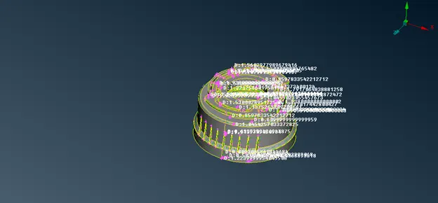
Fig: Measuring.
4. Since the Bottle cap has different and varying thickness, manual mid surface extraction must be carried.
5. The mid surface extraction can be carried out either by offsetting the existing face or by creating middle curves and then creating a new face at the center or by creating mid face directly.
6. Depending upon the type and shape of the geometry suitable method is preferred.
7. The plane surfaces can be offset directly and the openings must be filled by creating new surfaces.
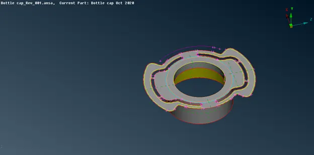
Fig: Offset of surface.
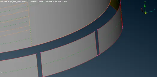
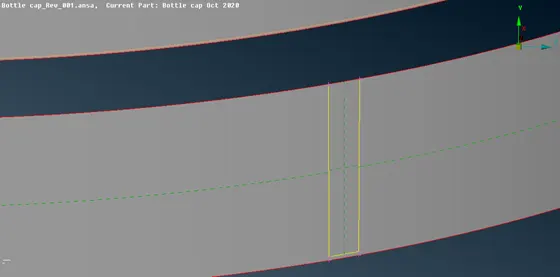
Fig: Joiniong by craeating new surface.
8. For the plain ribs the mid surface were created using faces_middle option.
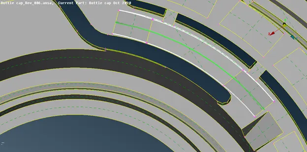
Fig: Faces_middle_single.
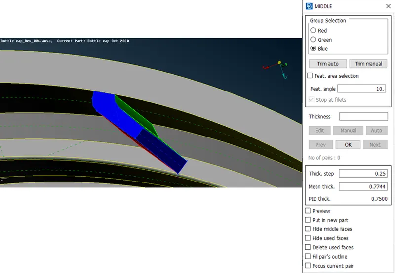
Fig: Faces_middle_multi.
9. For the threads and angular ribs, middle curve were created using curves_middle option and then the selected curves were projected to the surfaces and new surfaces were created using curves and projected cons to have the proper mid surface.
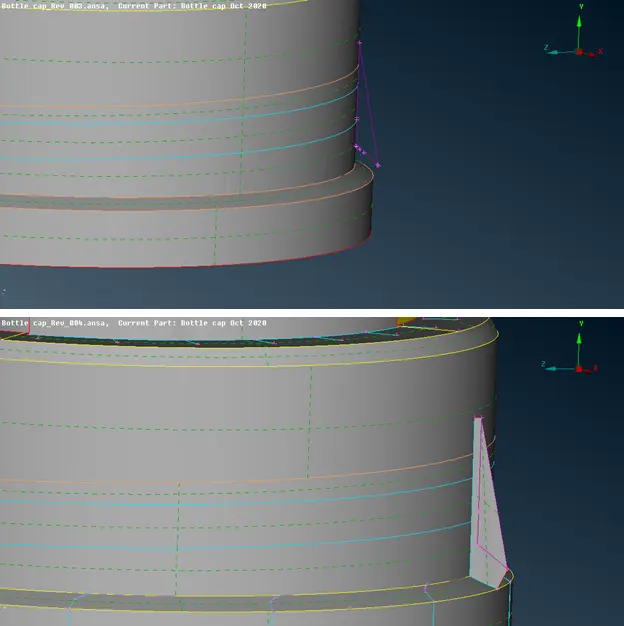
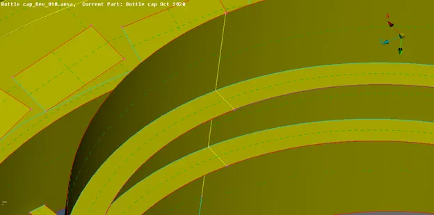
Fig: Midsurface using middle curves.
10. Since the component has similar multiple ribs instead of extracting individually rotate option is used by creating points on COG.
Create 2 COG (Center) points at different heights_Transofrm _copy_rotate_enter the no. of steps and angle_select the points as X and DX_ok.
11. The ribs must be extended till the surfaces either by extend option or by creating new surfaces by projecting the cons and additional surfaces must be trimmed off.
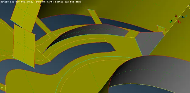
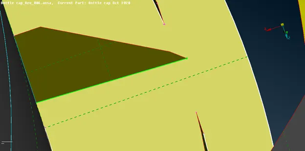
Fig: Extension of ribs.
12. If the gaps between the entities are below the minimum element length then the gaps merged to the existing surfaces in order to avoid the failure of elements.
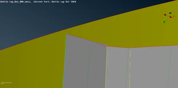
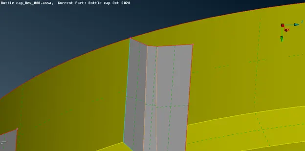
Fig: Before and after the filling of gap.
13. Orient the faces to unidirectional and enter the mesh and quality parameters as prescribed.
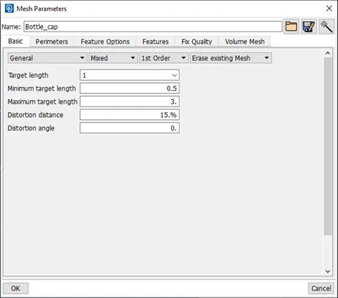
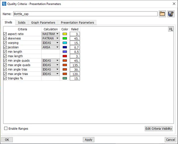
Fig: Mesh and quality parameters.
14. Mesh the component with surface by surface according to the given quality parameters.
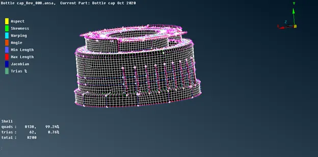
Fig: Meshing.
15. Create different properties according to the measured thickness and assign the same to the shell components.
16. Assign one material for all the properties and delete the unnecessary and switch on the bounds to view any openings.
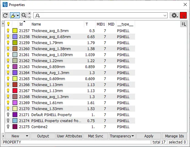
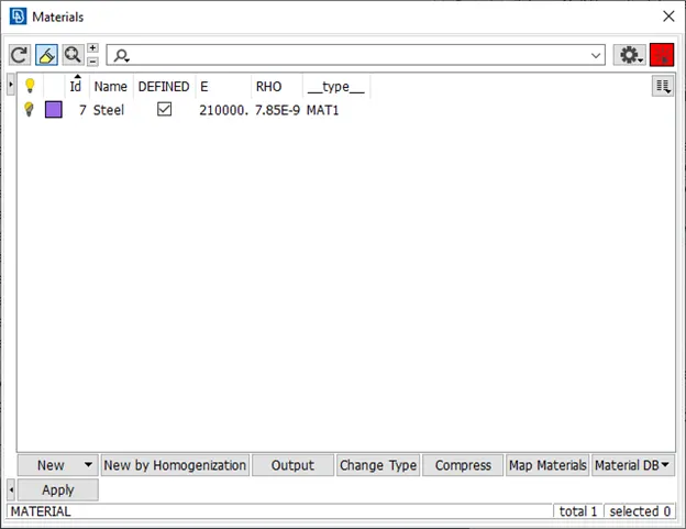
Fig: Assigning thickness and material.
17. To view the thickness representations switch on the shell as solid option.
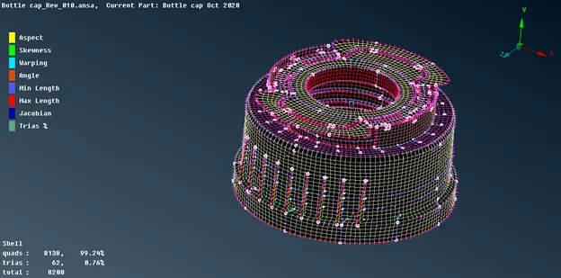
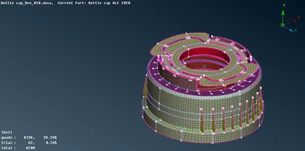
Fig: Finished model.
LEARNING OUTCOMES:
- The usage of tools like Intersect, Extend, Middle, Multi middle, Curves, Project etc,
- Extraction of manual mid surface for plastic components and varying thickness parts.
- Meshing of critical ribs and maintaining quality of elements.
- Application of rotate command.
CONCLUSION:
The given plastic bottle cap is meshed by maintaining the above said quality parameters by extracting mid surface manually. Thickness was assigned properly according to the parent geometry.
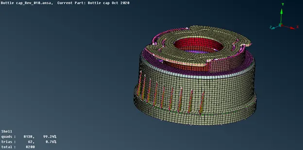
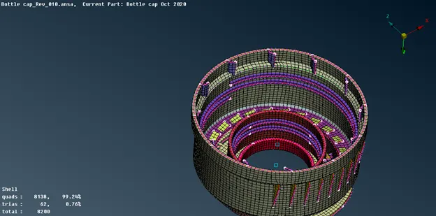
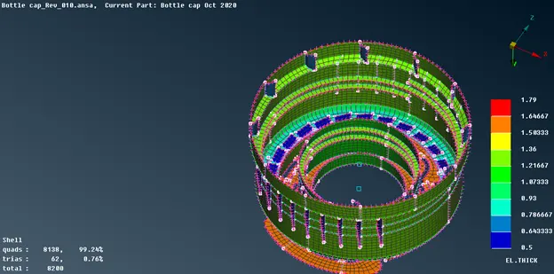
Fig: Final model.