Week - 4
Objectives:
- Implement control logic of a “washing machine” using Stateflow as per given sequence:
- If the power supply is available, the system gets activated.
- If the Water supply is not available, stop the process & indicate through the LED.
- Soaking time should be 200s followed by Washing time of 100s.
- Then rinsing happens for the next 20s & dryer runs for 50s.
- After all the processes have completed turn on the finished LED.
2. Make a Simulink chart for the “Gear shift” logic as per the below conditions:
Speed Range(kmph) Gear
0 to 15 1
16 to 25 2
26 to 40 3
41 to 60 4
Above 61 5
- Give speed input while the simulation is running & display the gear number.
Software Used: Simulink.
Implementing control logic of a “washing machine” using Stateflow:
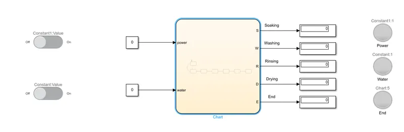
Simulink Model:
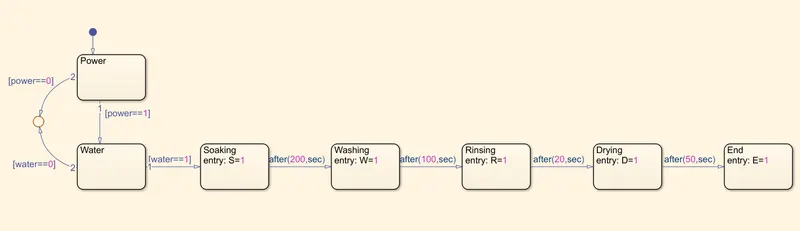
Stateflow (As shown inside chart):
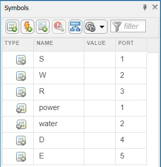
Symbol Pane:
Description of the Model:
- In the model, power and water are given as the input data.
- These inputs are controlled by the slider switches. The Off slider switch changes the value of the input to 0 which means there is no input. In the same fashion, the on slider switch changes the value of the input to 1 which suggests that there is input being provided to the system.
- S, W, R, D, E are taken as the output data. The alphabets S, W, R, D, represents whether soaking, washing, rinsing, drying operations respectively have been completed. E represents the end of the washing process.
- In the output, 0 represents that the process has not been completed. On the other hand, 1 represents that a particular process like soaking or washing has been completed.
- As you can see in the symbol pane, power and water represent the input ports 1 and 2 respectively. In the same fashion, S, W, R, D, and E represent the output ports 1, 2, 3, 4, and 5 respectively.
- The power and water values are connected to their respective lamps. If a particular slider switch is turned on, its respective lamp glows green. Otherwise, the lamp does not glow and stays grey. A similar lamp is also connected to indicate the end of the washing process.
Description of the State Flow:
- As we already know, power and switch inputs are controlled by the slider switches. These two inputs are directed towards the chart block.
- State blocks are used inside the chart to create a Stateflow according to the given criteria.
- The power is given as input to the chart and directed to the power state. Then, if power==1 (power slider switch is turned on), the state is directed towards the water state. If power==0 (power slider switch is turned off ), the state is directed towards the junction.
- At the water state, if water==1 (water slider switch is turned is on), it moves towards the next state i.e. soaking state. If water==0 (water slider switch is turned off), the state is directed towards the junction.
- After the value enters the soaking state, the value of S is changed to 1.
- After 200 seconds of soaking, the state is directed to the washing state. At entry into the washing state, the value of W is set to 1.
- After 100 seconds of washing, the state is directed towards the rinsing state. At entry into the rinsing state, the value of R is set to 1.
- After 20 seconds of washing, the state is directed towards the drying state. At entry into the drying state, the value of D is set to 1.
- After 50 seconds of drying, the state is directed towards the end state. At the entry into the end state, the value of E is set to 1. At the end state, the washing process is completed.
*** Before running the model, make sure that the stop time is set more than 370 seconds because the whole process takes at least 370 seconds according to the state flow as shown above. Here, we have taken stop time as 500 seconds.
Different states of operation:
- State 1: If the power supply is turned on and the water supply is not available or turned off.
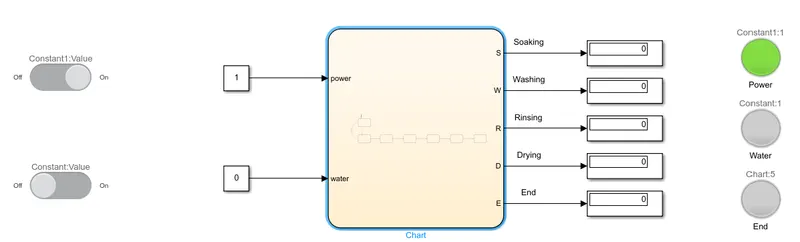
In this state, the power is on which is indicated by the green LED as shown in the figure above. It can be understood that there is no water supply since the water LED is not lit. Also, none of the processes like soaking, washing, etc. have been completed since all the values are displayed as zero.
- State 2: If the water supply is turned on and the power supply is turned off or not available.
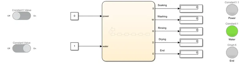
In this state, the water supply is on which is indicated by the green LED as shown in the figure above. It can be understood that there is no power supply since the power LED is not lit. Also, none of the processes like soaking, washing, etc. have been completed since all the values are displayed as zero.
- State 3: If both the power and water supplies are turned on.
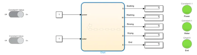
In this state, both the water supply and the power supply are on which is indicated by the glowing green LED's as shown in the figure above. Also, all of the processes like soaking, washing, etc. have been completed since all the values are displayed as one. Also, the end LED is glowing green which is an indication the entire process has been completed.
Making a Simulink chart for the “Gear shift” logic:
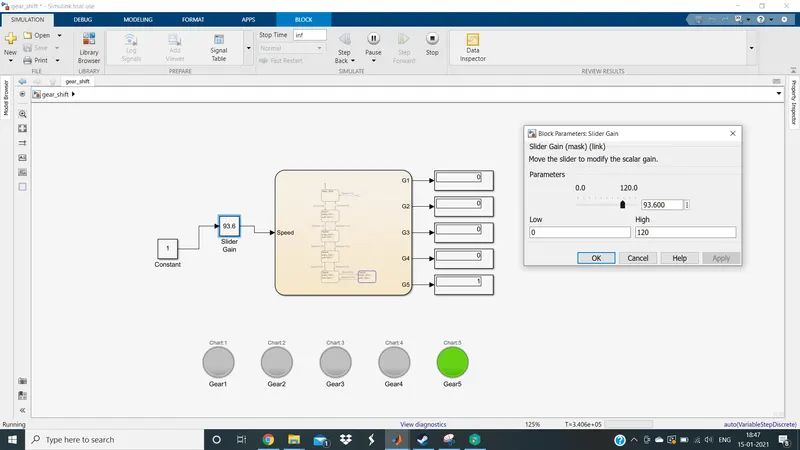
Simulink Model:
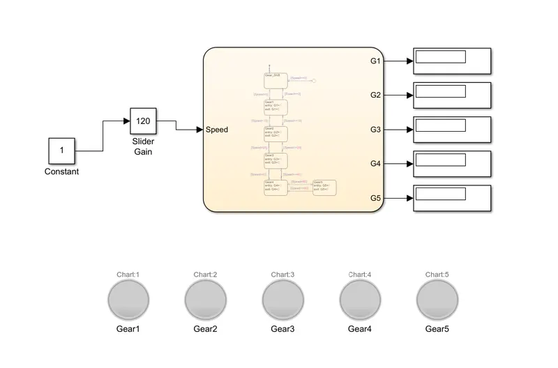
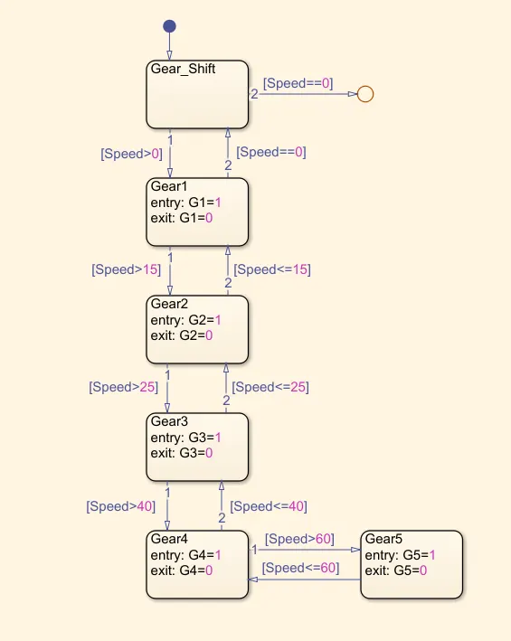
Stateflow (As shown inside the chart):
Symbol Pane:

Description of the Model:
- In the model, slider gain is given as the input data. The change in the slider gain input represents the change in the speed of a particular vehicle.
- G1, G2, G3, G4, and G5 are taken as outputs and they represent the first, second, third, fourth, and fifth gear respectively.
- The symbol pane also represents the same i.e. slider gain (speed) is the input and G1, G2, G3, G4, G5, G6 are output.
- In the output display, '1' on any one of the G's represent that particular gear is engaged. For example, if the output display of G3 shows 1 then it means that gear 3 is engaged.
- To sum up, as we change the speed of the vehicle using the slider gain, automatically the gear also changes according to the speed range. The lamp of the engaged gear is lighted up accordingly.
Description of the State Flow:
- The input values are given to the chart. The chart consists of state blocks to get a conditioned state flow.
- First, the input values that are generated are given to the Gear_Shift state. From there, if the Speed>0 kmph the Gear_Shift state proceeds to the Gear1 state. But if Speed==0 at the Gear_Shift state, the state proceeds to a junction, and flow is ended.
- As the state enters Gear1, the output value of the Gear1 state will be set as 1.
- At this time, the Gear1 lamp is activated.
- If the speed is greater than 15 kmph, at this time the state exits Gear1, and its value changes to 0. At the same time, the state enters Gear2, and its output value changes to 1.
- At this time, the Gear1 lamp is turned off and the Gear2 lamp is activated.
- If the speed is greater than 25 kmph, at this time the state exits Gear2, and its value changes to 0. At the same time, the state enters Gear3, and its output value changes to 1.
- At this time, the Gear2 lamp is turned off and the Gear3 lamp is activated.
- If the speed is greater than 40 kmph, at this time the state exits Gear3, and its value changes to 0. At the same time, the state enters Gear4, and its output value changes to 1.
- At this time, the Gear3 lamp is turned off and the Gear4 lamp is activated.
- If the speed is greater than 60 kmph, at this time the state exits Gear4, and its value changes to 0. At the same time, the state enters Gear5, and its output value changes to 1.
- At this time, the Gear4 lamp is turned off and the Gear5 lamp is activated.
*** Before running the model, make sure that the stop time is set as inf seconds because the simulation goes on until the user pauses or ends the simulation.
Different states of operation:
- State 1: As soon as the speed crosses 0 kmph, the gear changes to Gear1.
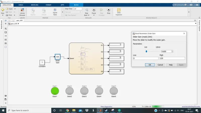
- State 2: As soon as the speed crosses 15 kmph, the gear changes to Gear2.
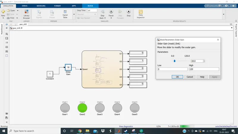
- State 3: As soon as the speed crosses 25 kmph, the gear changes to Gear3.
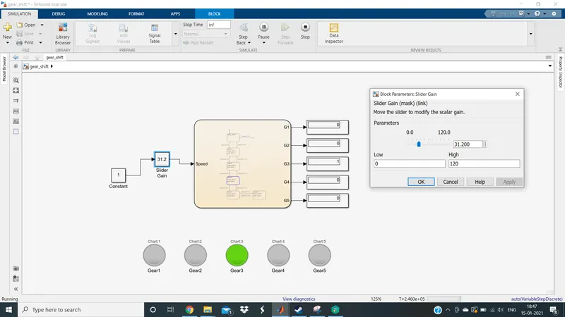
- State 4: As soon as the speed crosses 40 kmph, the gear changes to Gear4.
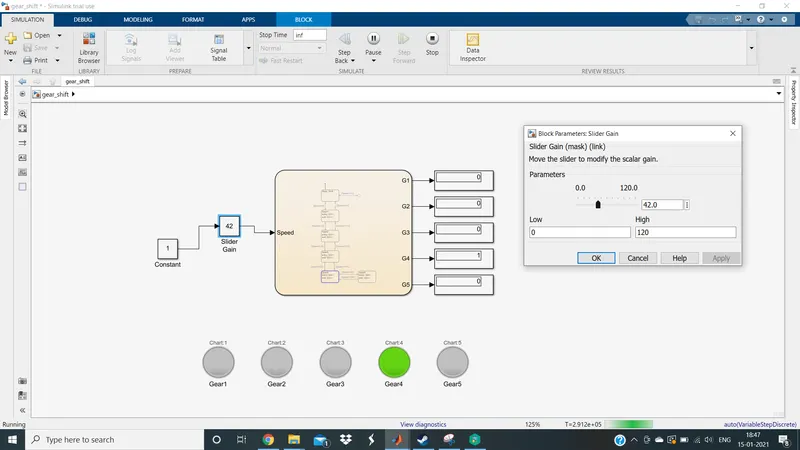
- State 5: As soon as the speed crosses 60 kmph, the gear changes to Gear5.