CREATING A SIMULINK MODEL OF A WASHING MACHINE AND A GEAR SHIFT INDICATOR USING STATEFLOW
AIM - 1
1. Implement control logic of a “washing machine” using Stateflow as per given sequence:
- If the power supply is available, the system gets activated
- If the Water supply is not available, stop the process & indicate through LED
- Soaking time should be 200s followed by Washing time of 100s.
- Then rinsing happens for the next 20s & dryer runs for 50s
After all the processes have completed turn on the finished LED
To create the required model we will be using the chart block in Simulink in which we will be using Stateflow for implementing the given control logic. The required theory has been explained below.
Simulink blocks required for this model is as follows-
1.  Lamp - This displays a color for the respective outputs. These blocks will be used to show that each process has been completed.
2.  Toggle switch - This acts as a switch for the water supply. The 'OFF' mode will input a value of 0 to the constant block which means the water supply has been cut off, the 'ON' mode will input a value of 1 to the constant block which means the water supply is turned on for the machine.
3.  Rocker switch - This acts as a switch for the power supply. The 'OFF' mode will input a value of 0 to the constant block which means the power supply has been cut off, the 'ON' mode will input a value of 1 to the constant block which means the power supply is turned on for the machine.
4.  Constant - This block will be connected with the toggle and rocker switches and acts as an input to the model
5.  Display - These blocks will display the outputs from the state flow.
Using the above blocks, a model of the washing machine has been created below.
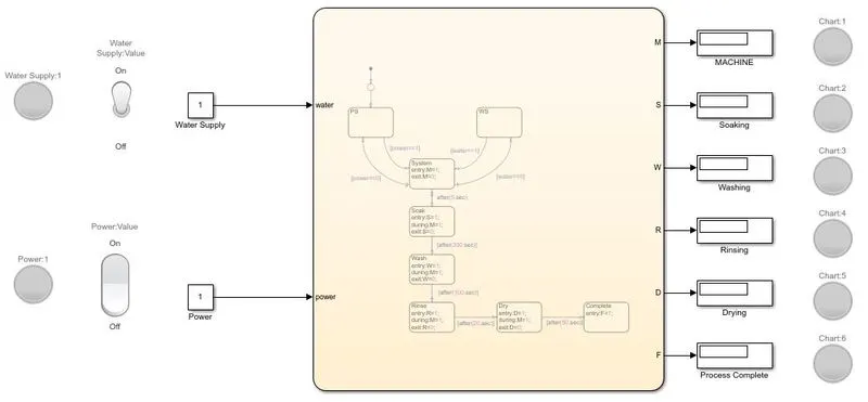
The blocks above are connected to a chart that consists of the control logic of the washing machine through the Stateflow method. The Stateflow is shown below.
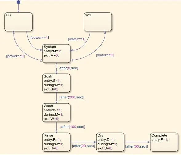
We can see that the control logic begins with the power supply state, once that condition is satisfied it moves onto the next condition which is the water supply state. If both the power and water supply states are satisfied the system will turn 'ON' or else it will be in the 'OFF' state. Once the system is turned 'ON', the lamp turns green indicating the machine's status. A condition specifying the delay for moving onto the next operation has been added i.e., soaking will take place for 200 seconds, washing will take place for 100 seconds, rinsing will take place for 20 seconds and drying will take place for 50 seconds after which the operations will be indicated as completed. The delays are specified as conditions using the 'after' statements.
RESULTS -
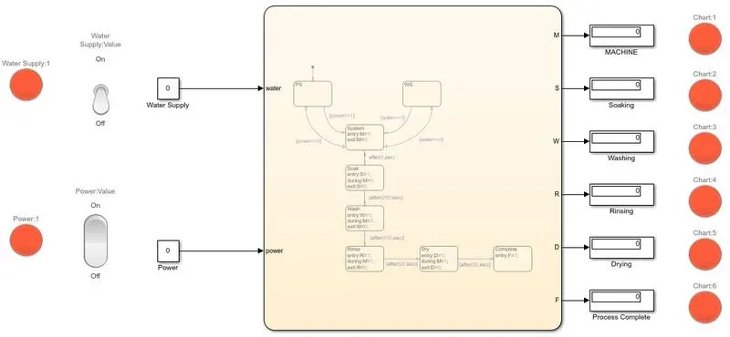
1. CASE-1- When both the power and water supply are turned off, we can observe that the lamps are indicating the color red, meaning the machine is turned off as shown in the below image.
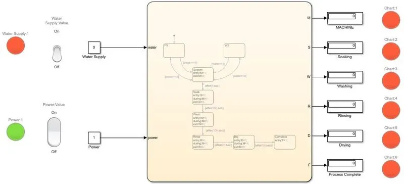
2. CASE-2-When the power supply is turned 'ON' and the water supply is turned 'OFF'
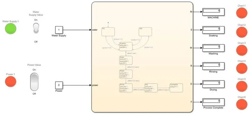
3. CASE-3 - When the water supply is turned 'ON' and the power supply is turned 'OFF'
Now we will look at how the machine will process when both the power and water supplies are turned 'ON'.
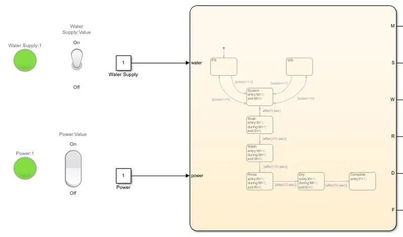
4. With both the power and water supplies turned 'ON', we can see the machine has been turned 'ON and the soaking process is in progress.
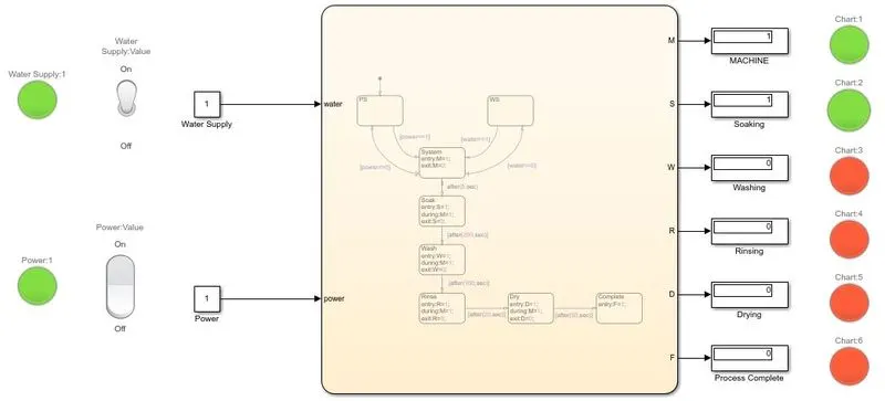
5. After the soaking process which takes place for 200 seconds as per the conditions given, it will move onto the next process, washing.
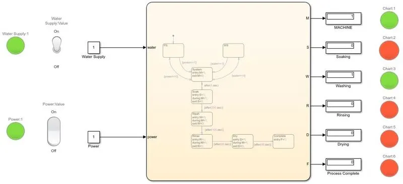
6. The washing takes place for 100 seconds and moves to the next operation, which is rinsing.
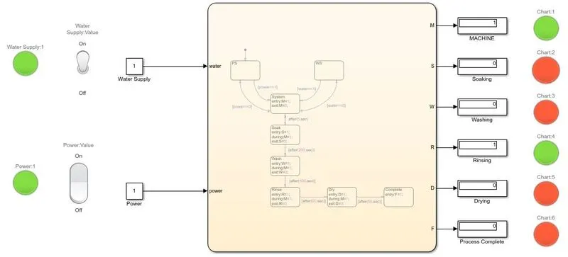
7. The rinsing operations take place for 20 seconds and then moves onto the drying process.
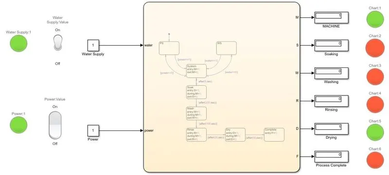
8. After 50 seconds of the drying operation, the process will be complete and it will be indicated through the lamp as shown below.
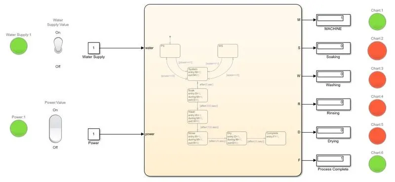
The Simulink file for the washing machine model has been attached below-
AIM - 2
2. Make a Simulink chart for the “Gear shift” logic as per the below conditions:
Speed Range(kmph) Gear
0 to 15 1
16 to 25 2
26 to 40 3
41 to 60 4
Above 61 5
Give speed input while the simulation is running & display the gear number.
To create the 'Gear shift' model, we will be using the chart block in Simulink in which we will be using Stateflow for implementing the given control logic. The required theory has been explained below.
The below-mentioned blocks have been used in the model.
1. 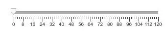 Slider - This block is used as a throttle in our model through which we can vary the input to the chart.
2. 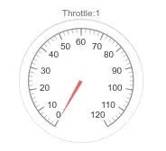 Guage - This block acts as a speedometer which shows the value of the input as we vary it through the slider block.
3.  Display (Dashboards) - This block also indicates the gear number active as we vary our input.
Using the above blocks we create a model with the given conditions as shown below.
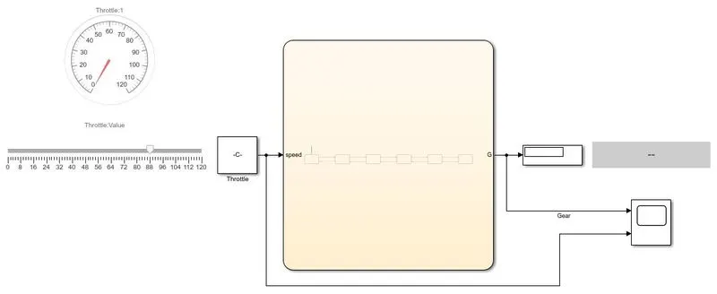
The blocks above are connected to a chart that consists of the control logic of 'Gear shift' through the Stateflow method. The Stateflow is shown below.
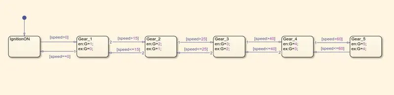
The first state would be the ignition 'ON' and then based on the conditions, the state keeps changing. If the speed is between 0-15, the gear will be shifted into 1st gear, if speed is between 16-25, the gear will be shifted into 2nd gear, if the speed is between 26-40, the gear will be shifted into 3rd gear, similarly, if speed is between 40-60 and above 60, the gears will be shifted into 4th and 5th respectively. Using this control logic and the model shown above, we can find our results.
RESULTS -
1. When you start to run the model and the speed on the slider is 0.
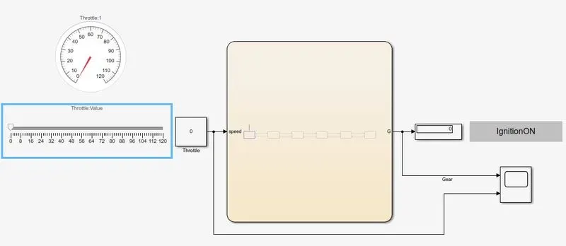
2. When you start increasing the value in the slider block to a value below 15 the display will indicate Gear_1.
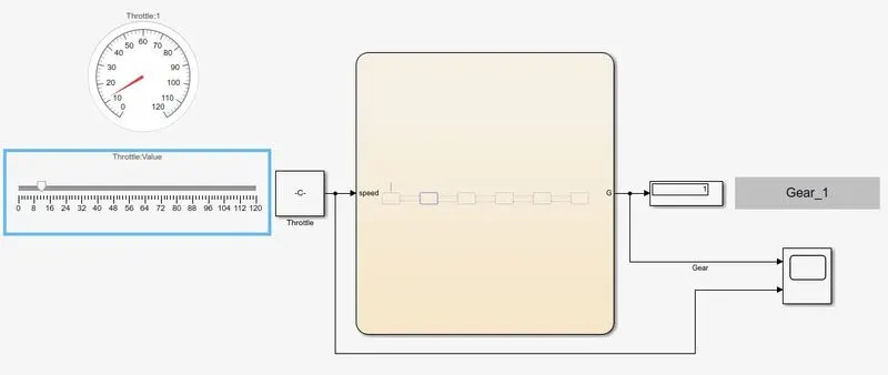
3. When you start increasing the value in the slider block to a value within the limit of 16-25, the display will indicate Gear_2.
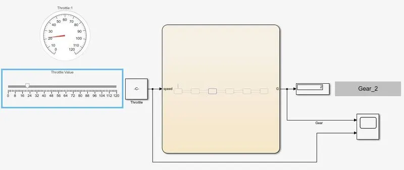
4. When you start increasing the value in the slider block to a value within the limit of 26-40, the display will indicate Gear_3.
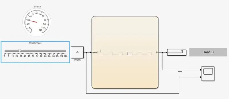
5. When you start increasing the value in the slider block to a value within the limit of 41-60, the display will indicate Gear_4.
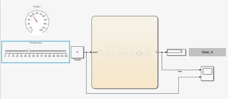
6. When you start increasing the value in the slider block to a value within the limit of 61 and above, the display will indicate Gear_5.
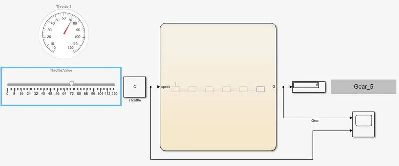
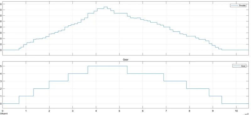
We had connected the input (throttle) and the output (Gear shift) to the scope to evaluate and understand how the model works and responds to the given conditions. The below plot shows the change in gears to speed and it satisfies the given conditions.
The Simulink file for the gear shift mechanism is attached below.
CONCLUSION -
We have created a working model of a washing machine and the gear shift mechanism for the given conditions using Stateflow to depict its control logic. The results of the same have been attached above.
REFERENCES -
2. https://www.youtube.com/watch?v=thBxzulFuyg&ab_channel=MATLAB