Project
AIM : To study the system – level simulation of an all- terrain vehicle and prepare a technical report explaining the model properties and comment on the results .
OBJECTIVE :
- To study the baja ATV model without dashboard
- To study the baja ATV model with dashboard
- To study the baja ATV model using lookup table without dashboard
- To study the the baja ATV model using lookup table with dashboard
THEORY:
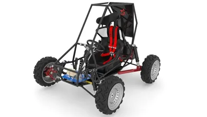
An all – terrain vehicle (ATV) also known as light utility vehicle which travels on low – pressure tires that have deep – threaded structures which helps the user in driving over muddy, rocky,wetlands with a seat that is operated by the user , and with handle bars for sterring control . As the name suggests it is designed to handle a variety of terrain than other vehicle. Different types of ATV are designed and manufactured for different purposes such as racing , military , hunting , emergency services and industrial usage .
COMPONENTS OF A BAJA ALL TERRAIN VEHICLE :
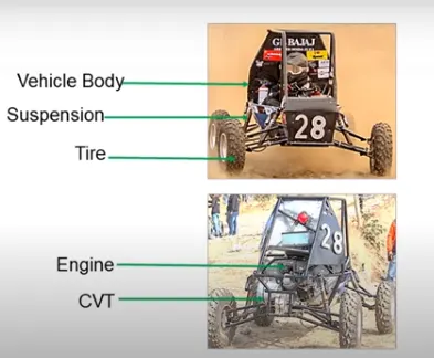
The following components of a baja all terrrain vehicle are :
- Vehicle body
- Suspension
- Tire
- Engine
- Continously variable transmission
CONTINOUSLY VARIABLE TRANSMISSION (CVT ):
Transmission is a mechanism that transmits power developed by the engine to the wheels of the car which is called as transmission system. For the vehicle to move forward at different speeds power changing devices is required to transfer the power developed by the engine to the wheels such devices are known as transmission. It consists of four types of transmission:
- Manual transmission
- Continuous variable transmission
- Semi – automatic transmission
- Automatic transmission
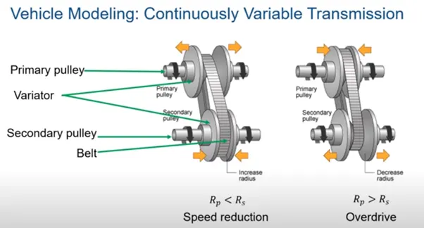
Nowdays most of the vehicles are fitted with continously variable transmission that ensures a smooth driving experience . CVT systems consists of two conical pulleys and a steel belt . The conical pulley can move which increases and decreases the diameter of the belt to change gear ratio for easy shifting of the gear into the needed ratio for increase in power and boost in fuel economy . One pulley in the cvt is connected to the engine and the other directs power to the wheels . The width of the pulleys chnages according to the power needed , as one increases and other decreases which allows cvt to deliver strong and seasmless acceleration .
BAJA ATV MODEL
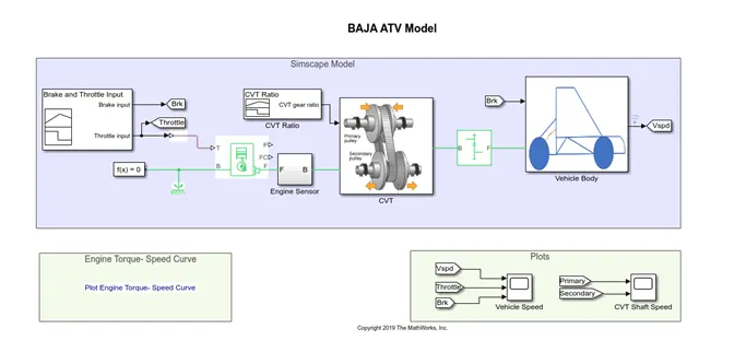
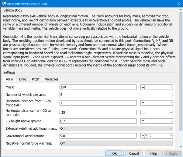
The above Simulink model of the CVT consists of signal builder, generic engine, motion sensors, vehicle transmission, vehicle body, tyres and solver configuration block etc. The CVT subsystem include transmission block, input and output shaft inertia and motion sensor as shown below. The initial engine speed is given as 1600 rpm, mechanical rotation for driven and driver pulley as 0.8 and 0.7 respectively. Mass of the vehicle is 250kg and 2 axles which connects the 4 wheels accordingly.
The following blocks used in the model are:
- Signal builder
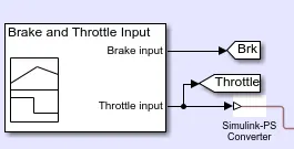
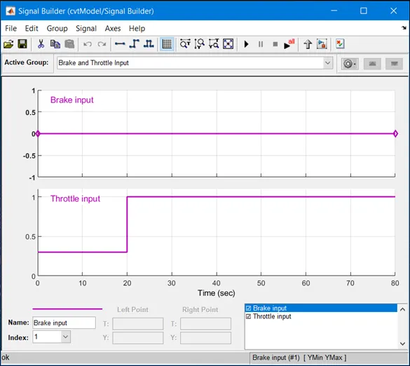
The signal builder helps to create interchangeable groups of piecewise linear signal sources which is used in the model. The above image depicts that 2 inputs are created one for brake and other one is for throttle. This is done by using signal builder block. Two “GOTO” blocks are used for brake and throttle. Simulink –PS convertor block is used since the inputs given are through Simulink blocks.
- Goto and from blocks
Goto block is basically an input signal that can pass to more than one from block. The input which is given to the go to block is received to the from block as if both the blocks were physically connected.


- The throttle input is connected to ‘T’ port of the generic engine through the Simulink convertor as shown below :
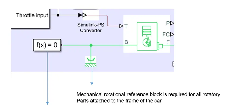
To this a solver configuration block is added. Each physical network is represented by connected simcape block diagram which requires solver settings information for simulation. Solver parameters are identified by solver configuration that the model needs before the simulation can run.
- Generic engine
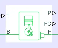
Generic engine is a system level model of spark ignition and diesel engines which is suitable for use at initial stages of modelling when basic parameters are available. The throttle signal T lies between 0 and 1 which specifies the torque demanded from the engine as a fraction of the maximum possible torque.
Connections F and B are mechanical rotational conserving ports where F is associated with engine crankshaft and B is for engine block. Connections P and FC are physical signal output ports through which engine power and fuel consumption rate are reported.
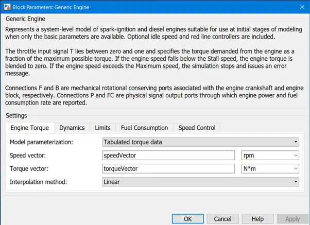
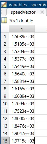
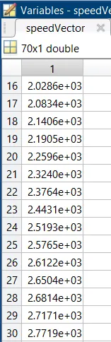
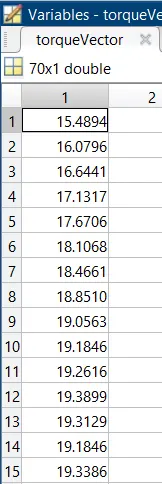
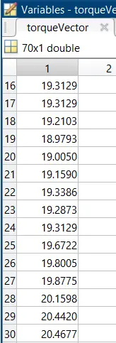
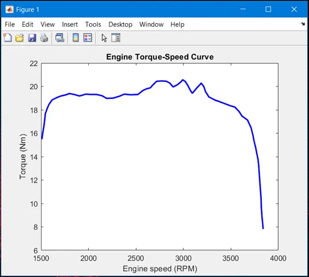
Speed vector and torque vector are the assigned parameters

Speed vector
Torque vector
- Engine sensor
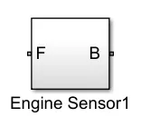
Engine sensor is used to record the output from the generic engine to the CVT. The subsystem block includes ideal rotational sensor and scope to display the values of speed by increasing or decreasing the throttle. Mechanical rotational reference and P-S terminator is connected to A and C of the rotational sensor.
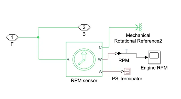
- Ideal rotational motion sensor
This block represents an ideal mechanical rotational motion sensor is a device which converts an across variable measured between two mechanical rotational nodes into control signal which is proportional to angular velocity or angle. It is an ideal sensor since it does not account for inertia, friction and energy consumption.
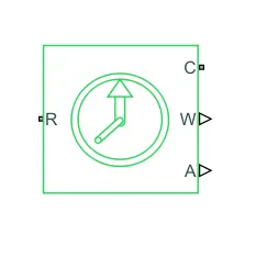
R and C connection in the block depict mechanical rotational conserving ports and W and A are physical signal output ports for velocity and angular displacement.
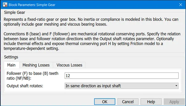
- Simple gear
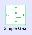
Simple gear represents a fixed –ratio gear and no inertia is modelled in this block. B and F connections are mechanical rotational conserving ports.
- Scope
Scope is used for viewing the graphs of the signals after the simulation is run
CVT SUBSYSTEM
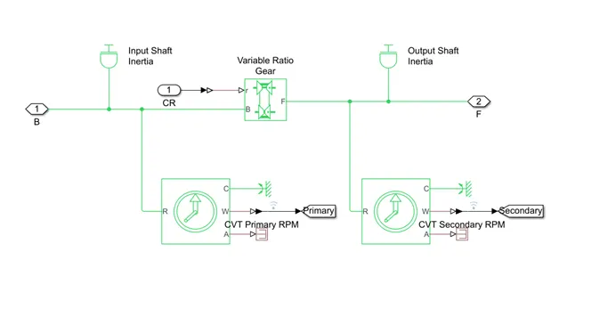
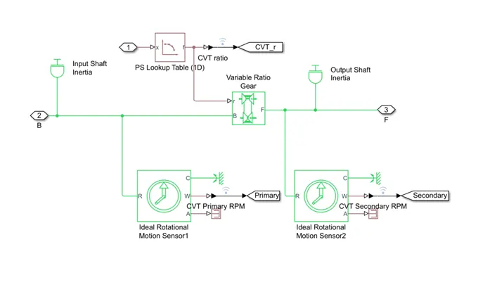
In the above model the CVT subsystem consists of the following blocks:
- Inertia block
It has one or two mechanical rotational conserving ports. For this block the positive direction is from its port to the reference point. This means that the inertia torque is positive if inertia is accelerated in the positive direction.
It is also described with the following equation:
T =Jdω/dt
Where,
T = inertia torque
J= inertia
ω = angular velocity
t = time
- Variable ratio gear
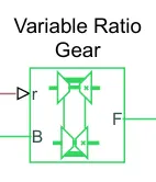
The variable ratio gear box represents a gear box which dynamically transfers motion and torque between two connected driveshaft axes, base and follower. In this block B and F are rotational conserving ports which represents the base and follower driveshafts. R is the physical signal input port where unit less variable gear ratio are specified as a function of time.
VEHICLE BODY SUBSYSTEM
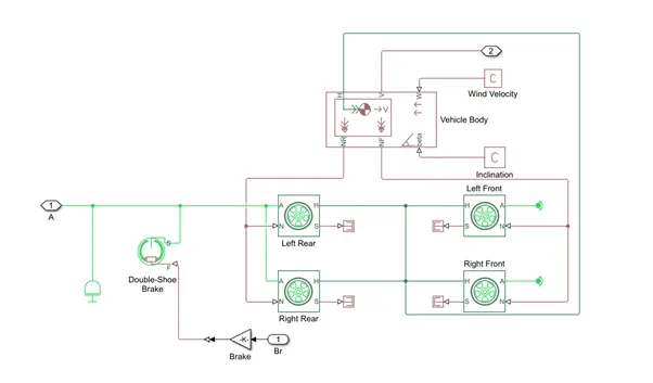
The vehicle body represents complete vehicle assembly with all the inputs required to operate the engine with varying parameters. The subsystem of the vehicle has following blocks:
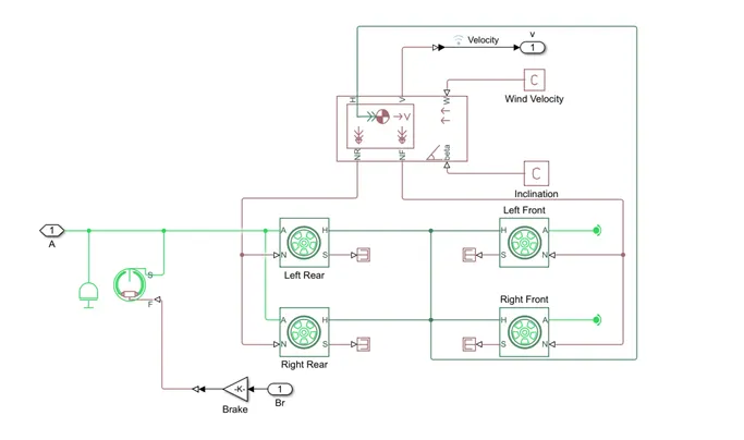
- Vehicle body
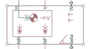
Vehicle body represents two- axle vehicle body in longitudinal motion. This block considers body mass, road incline, aerodynamic drag and weight distribution between axles due to acceleration and road profile. In response to system changes mass, inertia and center of gravity can vary for the course of simulation. The vehicle can have the same or different number of wheels on the same axle.
Connection H is mechanical translation conserving port which accounts for the horizontal motion of the vehicle body. Connection NF, V, NR are the physical signal output ports for the vehicle velocity and front and rear normal wheel forces. Connections W and beta are physical signal input ports that corresponds to headwind speed and road inclination angle.
- Wheels
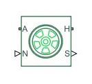
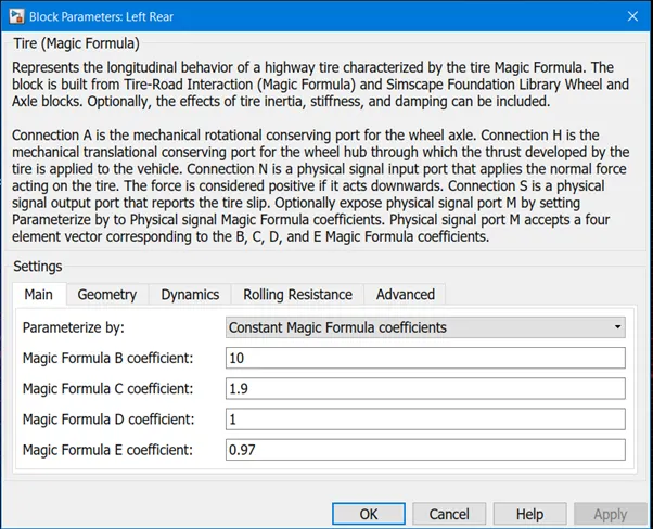
It represents the longitudinal behaviour of the tyre which is characterized by magic formula. Tire dynamics are modelled under constant or variable pavement conditions. To increase the life and performance of the tyre model properties such as tire compliance, inertia and rolling resistance are specified. But these properties can increase the complexity of the tyre model and slow down the simulation.
Connection A is the mechanical rotational conserving port for wheel axle. Connection A is mechanical rotational conserving port for the wheel axle. Connection H is mechanical translation conserving port for the wheel hub by which the thrust is developed by the tyre which is applied to the vehicle. Connection N is physical signal input port that is applied to the normal force acting on the tyres. Connection S is a physical signal port that reports tyre slip.
- Double Shoe brake
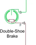
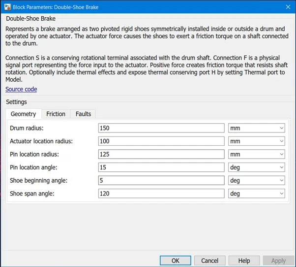
Double show brake block depicts a frictional brake with 2 pivoted rigid shoes which is pressed against a rotating drum which produces brake. In a diametrically opposed configuration the rigid shoes sit inside or outside the rotating drum .Positive actuating force causes the rigid shoes to press against the rotating drum. Viscous and contact friction between the drum and rigid shoe surfaces which causes the rotating drum to decelerate.
Connection S is a conserving rotational terminal connected with the drum shaft. Connection F is a physical signal port which is the force input to the actuator.
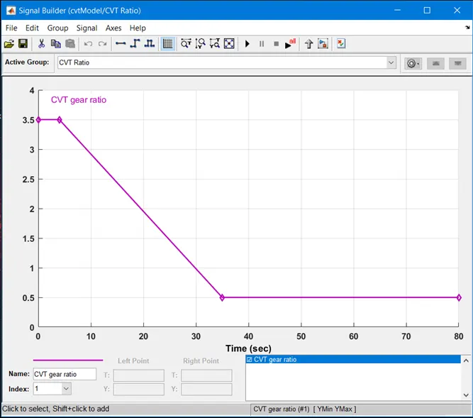
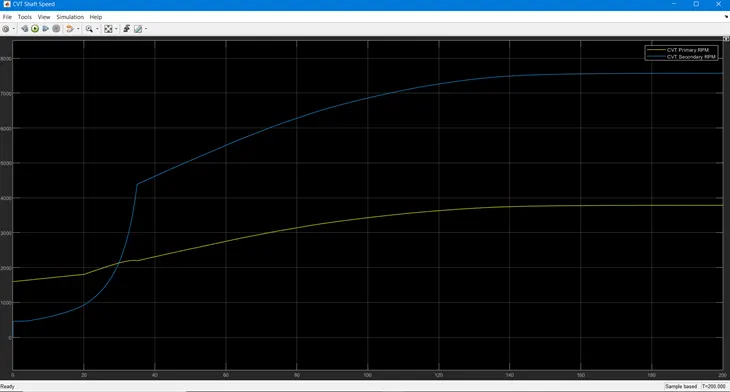
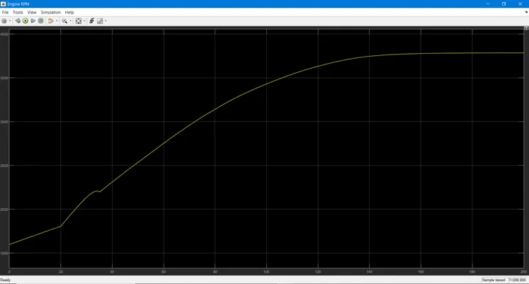
As shown below the signal builder is used as input for brake, throttle and gear ratio. Brake input is maintained as zero for the full simulation. The throttle input is given as 0.3 till 20 seconds and increases to 1 for the full simulation. The throttle input is used to control the flow or amount of fuel into the engine. If the throttle value increases the flow of fuel increases to the I.C. engines which in turn increases the power of the engine. The gear ratio is maintained as 3.5 for 5 seconds and decreases steeply to 0.5 which is then maintained constant for the full simulation as shown below.
Explanation of the model
- A signal buider block is used as in input for brake and throttle . The output of the throttle is connected to the genric engine via the simulink –ps convertor and the output from the CVT gear ratio to the CVT block
- The output port F from the generic engine is connected to the engine sensor and the output from the engine sensor is connected to the CVT block
- The inputs from the CVT gear ratio is given to the CVT block and the engine parameters are specified and provides input to the wheels . The power from the CVT is transferred to the wheels with the help of simple gear connected between them .
- The power output from the simple gear block is attached to the input of the vehicle body where the values of braking and throttling are checked and in the scope the signals are displayed for the particular effect .
- Goto and from block is attached to the vehicle body and the scope respectively so that the performance curve is displayed when brake and throttle is applied to the vehicle.
PLOT OF ENGINE TORQUE VS SPEED
OUTPUT:
VEHICLE SPEED:
CVT SHAFT SPEED:
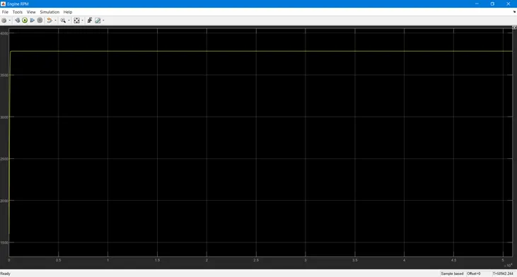
ENGINE RPM :
STUDY-2
BAJA ATV MODEL WITH DASHBOARD
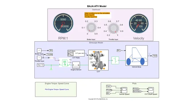
The above model presents BAJA ATV MODEL WITH DASHBOARD which consists of brake input and the throttle input in the dashboard instead of the signal builder as in the previous model. The blocks and the subsystem are the same as in the BAJA ATV model without dashboard.
Circular gauge block is used which acts as a speedometer where the values can be displayed from the input knob.
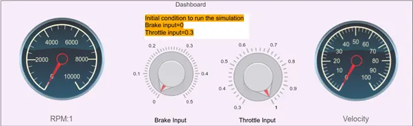
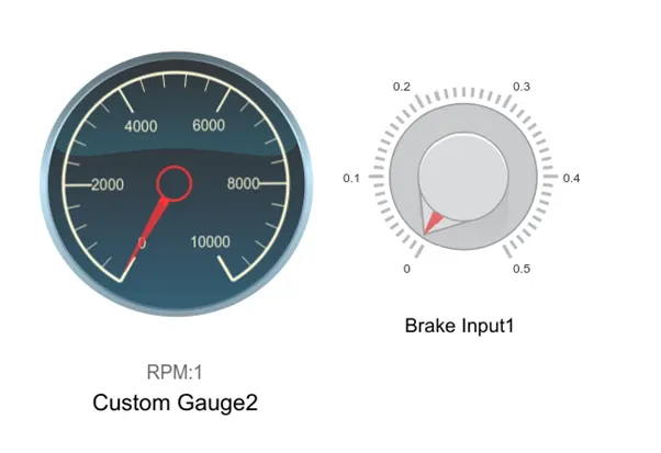
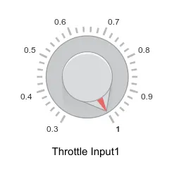
The knob is used to provide the input values for brake and throttle where the knob can be set as per the required condition.
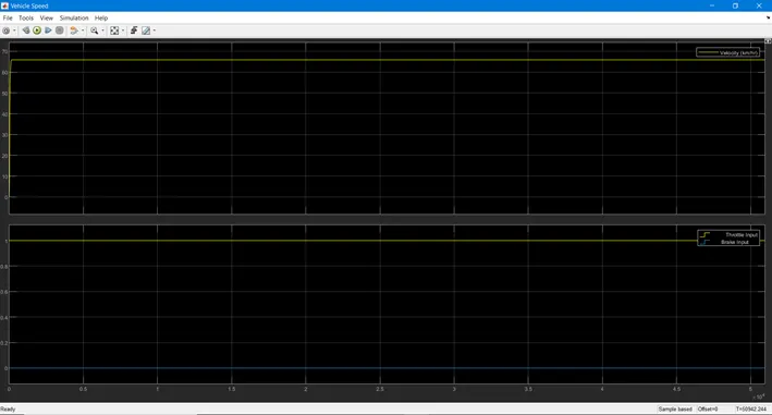
In this model inputs are provided using a knob block which can be rotated to increase or decrease the input values. The reason behind using dashboard is to examine the result by varying the input of brake and throttle which shows the velocity and speed of the engine. The gear ratio is maintained as 3.5 for 5 seconds and decreases steeply to 0.5 and is maintained constant for the full simulation. As the brake input varies from 0-0.5 the velocity and speed increases accordingly. It is observed that by increasing the throttle the vehicle speed and the shaft speed increases.
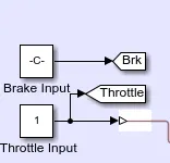
In this model the input given for brake and throttle is given as constant instead of signal builder block in the previous model as shown below:
VEHICLE SPEED:
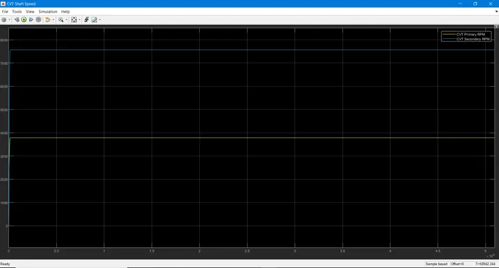
CVT SHAFT SPEED:
ENGINE RPM :
STUDY-3
BAJA ATV MODEL USING LOOK UP CHART WITHOUT DASHBOARD
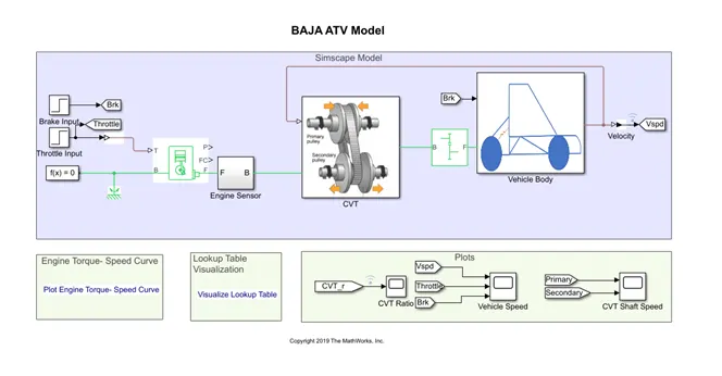
Simulink model of CVT as shown above consists of step time, motion sensor, vehicle transmission, vehicle body, tyre and solver configuration block etc. CVT subsystem includes look up table, transmission block, and input and output shaft inertia and motion sensor .The vehicle body subsystem includes vehicle body block, double shoe brake and tyres. The initial engine speed is given as 1600 rpm, mechanical rotation for driven pulley and driven pulley as 0.8 and 0.7 respectively. The mass of the vehicle as 250kg and 2 axles which connects 4 wheels accordingly.
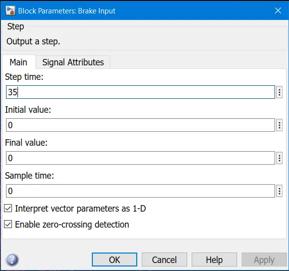
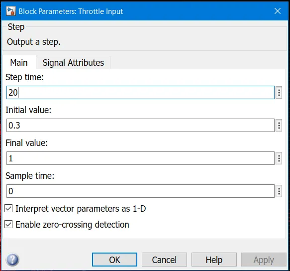
The input block parameters for brake and throttle for this model can be seen below:
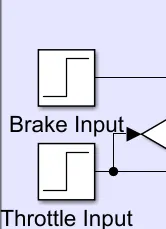
- Brake input parameters
- Throttle input parameters
- Look up table
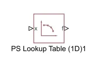
A look up table is an array of data that maps input values to output values by which a mathematical function will be approximated. If look up table does not accurately define the input values, Simulink helps in estimating the output values using three methods
- Interpolation
- Extrapolation
- Rounding
- Interpolation
It is the process of estimating the values that lie between known data points.
- Extrapolation
It is the process of estimating values that lie beyond the range of known data points
- Rounding
It is the process where the values are approximated by altering its digits according to a known rule.
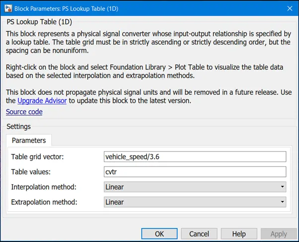
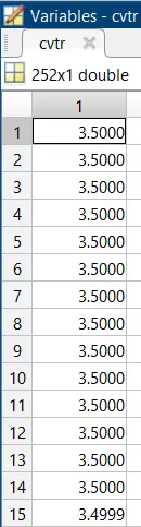
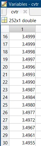
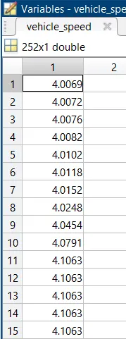
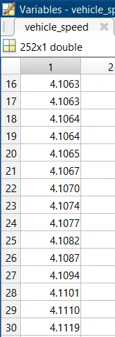
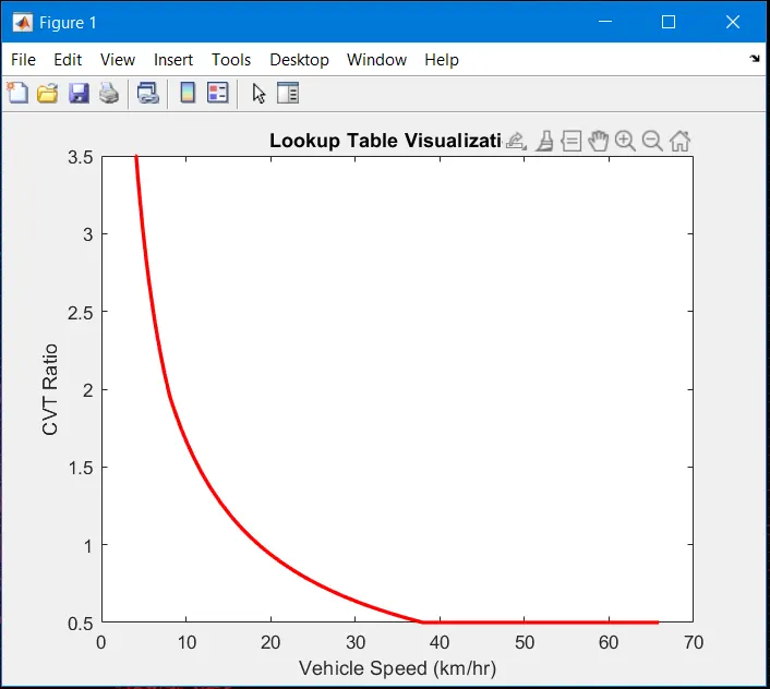
In this model the gear ratio is input via the look up table linked directly from .mat external file. The look up table file consists of CVT ratio and vehicle speed, CVT ratio varies based on 1D look up table.
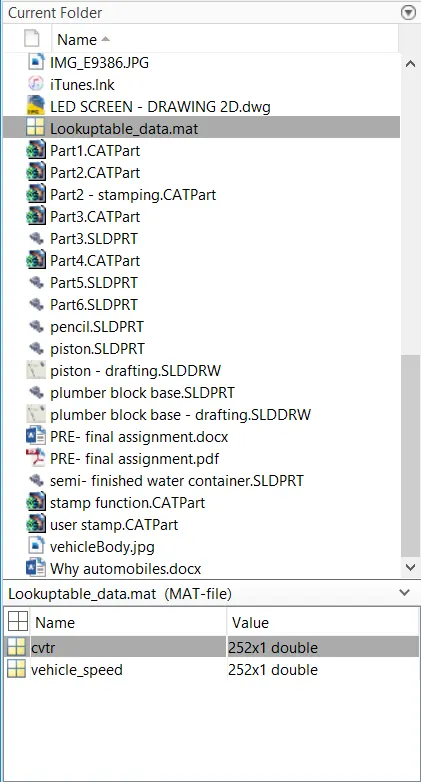
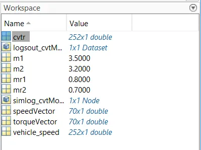
The values of CVTr
Values of vehicle speed
CVT SUBSYSTEM
VEHICLE BODY SUBSYSTEM
LOOK UP TABLE
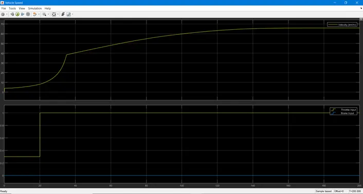
VEHICLE SPEED:
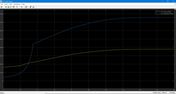
CVT SHAFT SPEED:
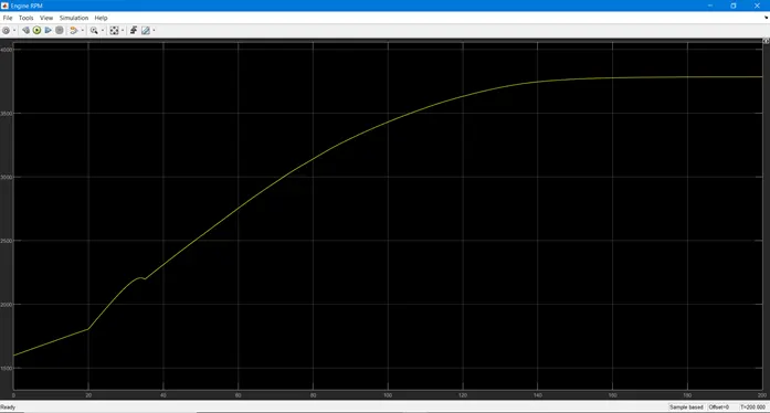
ENGINE RPM
STUDY-4
BAJA ATV MODEL WITH DASHBOARD USING LOOK UP TABLE
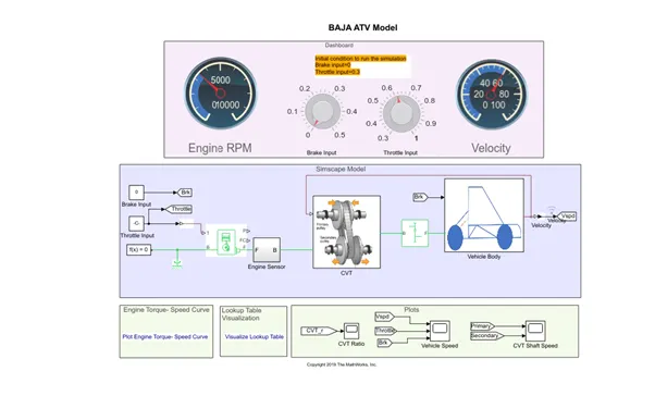
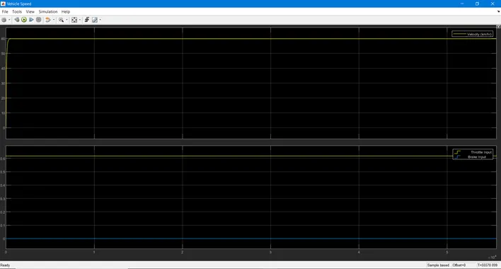
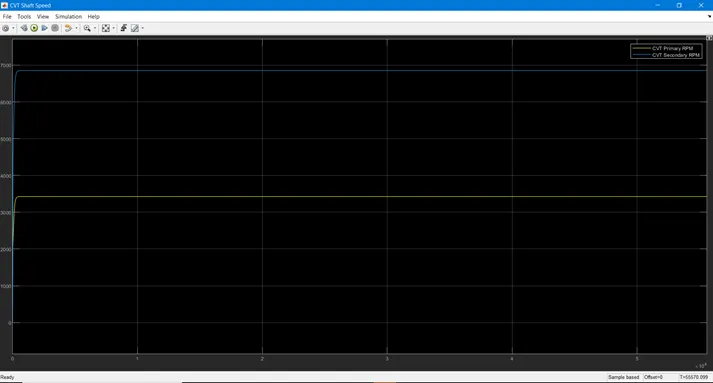
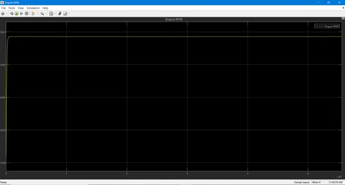
In the above model BAJA ATV MODEL WITH DASHBOARD using look up table which consists of throttle meter and brake input in the dashboard which is assigned as constant block. Rest of the blocks and subsystem are the same as compared to the BAJA ATV MODEL WIHTOUT DASHBOARD. The reason behind using dashboard is to examine the result by varying the input of brake and throttle which shows variation in the velocity and speed of the engine. The gear ratio is given by lookup table, Simulink gets the input value from the lookup table and the result is obtained according to the lookup table. As the brake input varies from 0-0.5 the velocity and speed decreases which in turn decreases the gear ratio. When the throttle is increased the velocity and speed of the engine and the shaft increases. The transmission as primary and secondary pulley, where the radius of the primary pulley increases by compacting which makes the radius of the secondary pulley decreases. As the gear ratio varies torque also varies. Gear ratio is directly proportional to torque, which increases by increasing the gear ratio. When the torque is maximum speed and velocity decreases.
VEHICLE SPEED:
CVT SHAFT SPEED:
ENGINE RPM:
CONCLUSION:
- From the above results we can infer that the BAJA ATV model was stimulated successfully
- CVT shaft speed, velocity and engine speed is directly proportional to throttle input and inversely proportional to the brake input.
- CVT primary shaft speed and CVT secondary shaft speed depends upon their radius
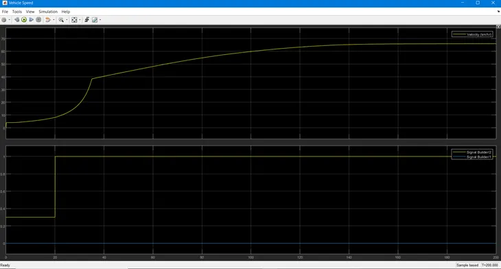
- Increase in braking value decreases the vehicle speed. Increase in throttle value leads to increase in vehicle speed.