Week 4.1: Project - Steady state simulation of flow over a throttle body
Steady state simulation of flow over a throttle body
- Aim:
- Perform steady-state flow simulation over a throttle body in a elbow pipe.
- Perform the simulation by using the pressure inlet- pressure outlet boundary conditions.
- Post-process the results and plot the necessary graphs.
- Create a flow animation to depict the flow characterestics.
- Introduction:
1. Throttle:
A throttle is the mechanism by which fluid flow is managed by constriction or obstruction.
An engine's power can be increased or decreased by the restriction of inlet gases (by the use of a throttle), but usually decreased. The term throttle has come to refer, informally, to any mechanism by which the power or speed of an engine is regulated, such as a car's accelerator pedal. What is often termed a throttle (in an aviation context) is also called a thrust lever, particularly for jet engine powered aircraft. For a steam locomotive, the valve which controls the steam is known as the regulator.
2. Throttle body:
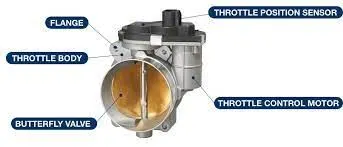
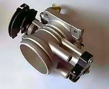
In fuel injected engines, the throttle body is the part of the air intake system that controls the amount of air flowing into the engine, in response to driver accelerator pedal input in the main. The throttle body is usually located between the air filter box and the intake manifold, and it is usually attached to, or near, the mass airflow sensor. Often, an engine coolant line also runs through it in order for the engine to draw intake air at a certain temperature (the engine's current coolant temperature, which the ECU senses through the relevant sensor) and therefore with a known density. The largest piece inside the throttle body is the throttle plate, which is a butterfly valve that regulates the airflow.
- Procedure:
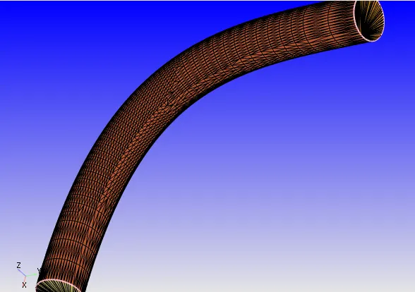
1. Upload the stl file onto converge studio, remove the thicknes by using the delete option under repair.
2. Close the open edges by creating inlet and outlet surfaces to close the geometry.
3. Asssign boundary flagging for each boundary appropriately.
4. Assign throtlle boundary flagging by hiding the outer wall partially and then assign boundary to throttle by choosing surface select.
- Case setup:
1. Application type: time based
2. Materials:
a. Gas simulation: air
b. Global transport properties: Deafult
c. Species: O2 and N2
3. Simulation parameters:
a. Run parameters:
Steady state solver, full hydrodynamic, compressible
Steady state mointor turned ON:
i. Average velocity
ii. Total pressure
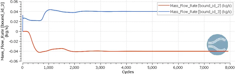
iii. Mass flow rate
b. Simulation time parameters:
- End time- 15000 cycles
- Time step- 1e-6
- min time step- 1e-6
- max time step- 1
- Convection CFL number- 0.5
c. Solver Parameters [Steady-State]-
- Solver type- density based solver
- Equations- pressure- change preconditioner to none
- steady state solver control- convection CFL limit- 0.5
4. Boundary Conditions-
a. Inlet- Inflow
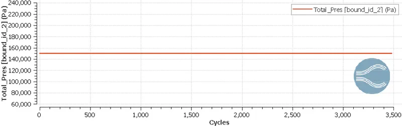
- Total pressure- 1.5e5 Pa
- Initial temp- 300K
- Species boundary condition- add air
b. Outlet- Outflow
- Pressure- 1e5 Pa
- Backflow - temp= 300k
- add air
c. Elbow wall - Walls
no slip condition- The contact region between wall surface and fluid region tends to create high friction and create a 0 velocity of fluid flow, and due to viscosity of fluid, the fluid layers tend to undergo shear stress and have high pressure and overlap on eachother which eventually forms a fully developed region where velocity is max and constant and having low pressure.
d. Throttle body: Wall- Since throttle is a separate surface creating an obstruction it acts as a wall, and since it is a steady-state simulation as the throttle is kept stationary.
5. Initial Conditions and Events:-
- Regions and Initialization:
Pressure- 1.5e5 Pa
Temperature: 300K
Add- air
6. Physical Models:-
- RNG k-epsilon
7. Grid Control:-
a. Base Grid:
dx = 2e-4m, dy = 2e-4m, dz = 2e-4m
b. Embedding:
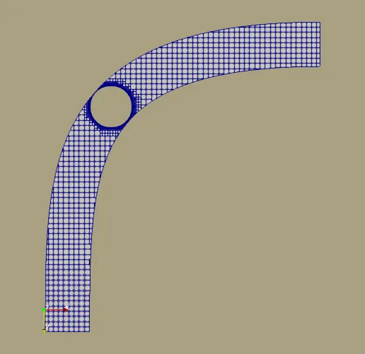
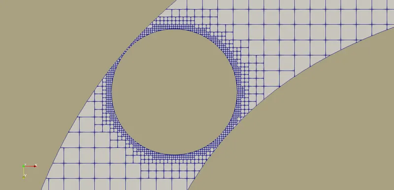
- Boundary type, Near the Throttle body, permanent mode embedding.
Scale- 3
Number of layers- 2
Embedding is the means by which we can refine the mesh to a value that is lower than the prevalent base size. This is especially useful if we are looking to refine near wall to capture the boundary layer or the wake of a body more accurately.
8. Post-Processing:-
- Post Variable Selection:
Select the parameters needed to be post processed.
- Output files:
We need to set a time interval for the files to be saved during each set of iterations. It is best suited to have a min of 100 saved files for every simulation. Therefore we need to calculate the time interval for writing the output files based on our end time given in run parameters.
Restart files help in restoring the files if there is a sudden power cut/ crash which is not helpful or might end up loosing the entire data, therefore the restart files helps in resuming the simulation form the point we lost contact. Restart files time interval can be same as the writing files interval which is safe and healthy.
In this case- since the end time is 15000, we can have a time interval of 150 and the total files created will be 100.
- Results:
1. Mesh grid:
- Model mesh:
- Embedded mesh at the throttle body:
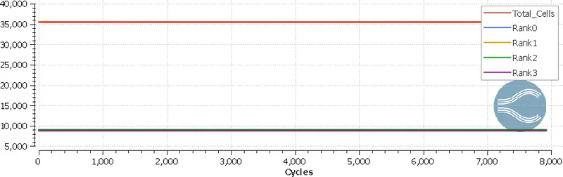
- Cell count:
2. Velocity contour:
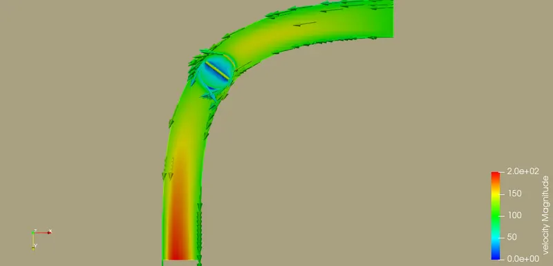
- Complete model:
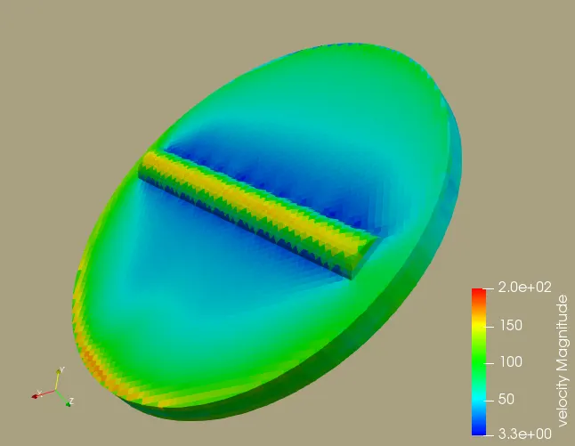
- Throttle body:
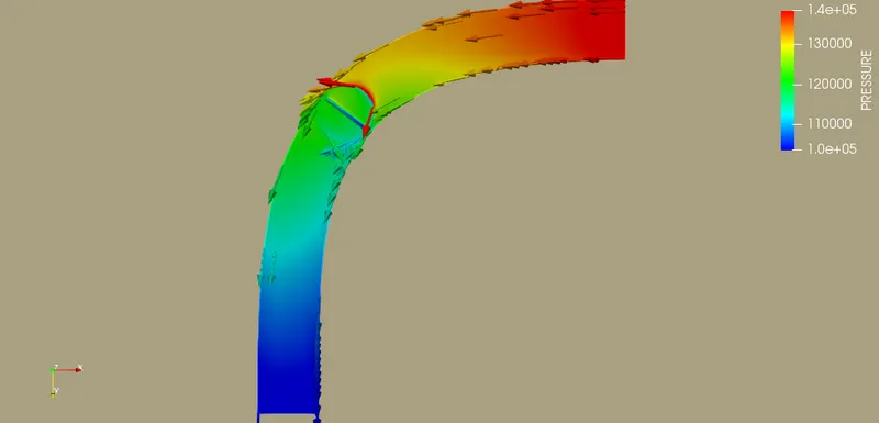
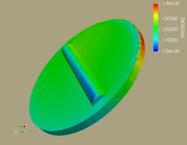
3. Pressure contour:
- Complete model:
- Throttle body:
3. Mass flowrate:
4. Inlet:
- Total pressure:
- Static pressure:
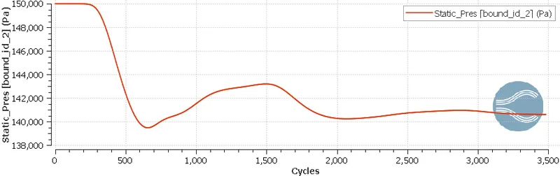
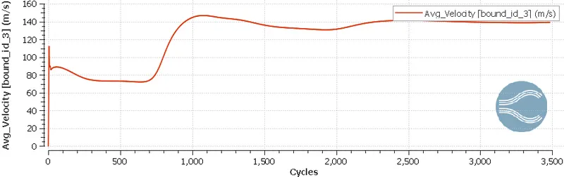
- Average velocity:
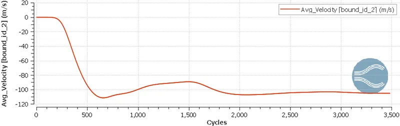
5. Outlet:
- Total pressure:
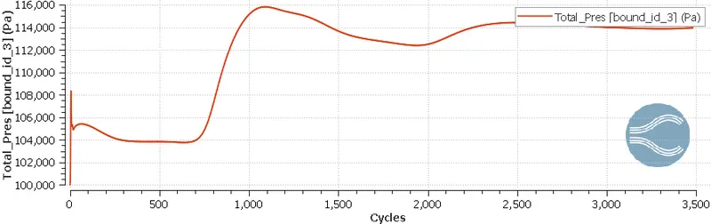
- Static pressure:
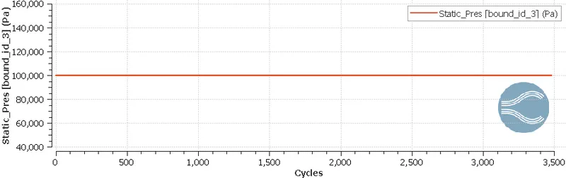
- Average pressure:
6. Flow animations:
- Velocity:
- Pressure:
- Discussions:
1. Flow simulation over a throttle body is achieved at steady-state where the throttle body is kept stationary.
2. As the flow develops, Velocity tends to increase and due to the no-slip conditions of the walls and gives an extra speed at the flow center due to viscous effects.
3. Wake region is developed at the throttle body due to the flow separation, causing low pressure gradients and creating recirculation regions.
4. Embedded mesh at the throttle helps achieving accurate results, wake regions and the no slip conditions at the boundary regions.
5. Since there is no change in the angle of throttle, there is not much significant change in the flow physics.