Week 4.1: Project - Steady state simulation of flow over a throttle body
Aim --> Steady-state simulation of flow over a throttle body.
Introduction
To regulate the power output from an engine there has to be some restriction of how much fuel-air mixture reaches the cylinders. One way to do this is to use some kind of valve that restricts the air, fuel is then regulated to get the correct fuel-air mixture. The most common valve is of butterfly type and is used in almost every car engine manufactured today, the valve is sketched in the figure. The throttle plate rest angle α0 is larger than zero to prevent wall binding.
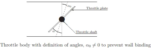
Throttle body mechanisms are used to control the fluid flow rates. It is a thermodynamically Irreversible process and constant enthalpy process. Throttling was first studied in joule's experiment.
Geometry
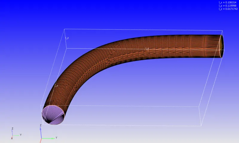
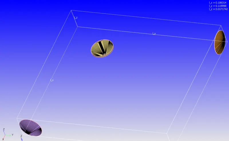
--> We have a curved pipe geometry with a throttle body placed inside the geometry.
Boundary
- Inlet
- Outlet
- Elbow wall
- Throttle wall
Case Setup
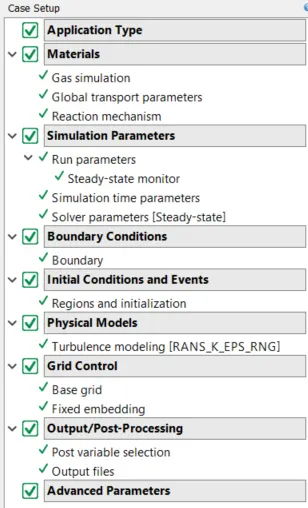
- Application Type --> Time-based
- material --> Air
- Solver Run parameters
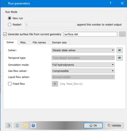
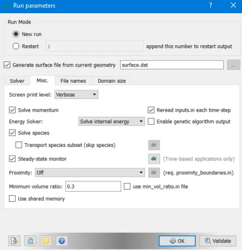
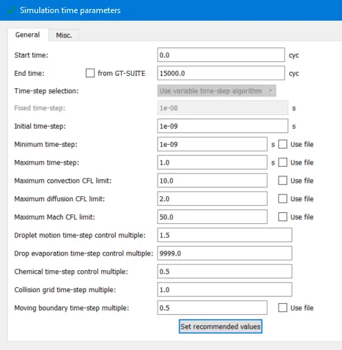
- Simulation time parameters
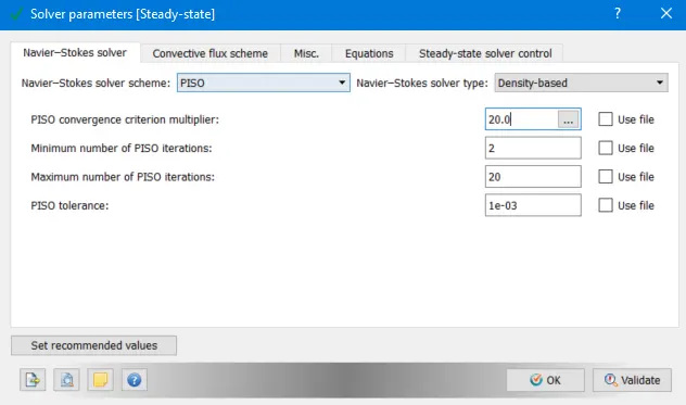
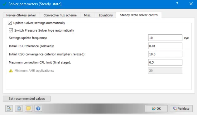
- Solver Parameters
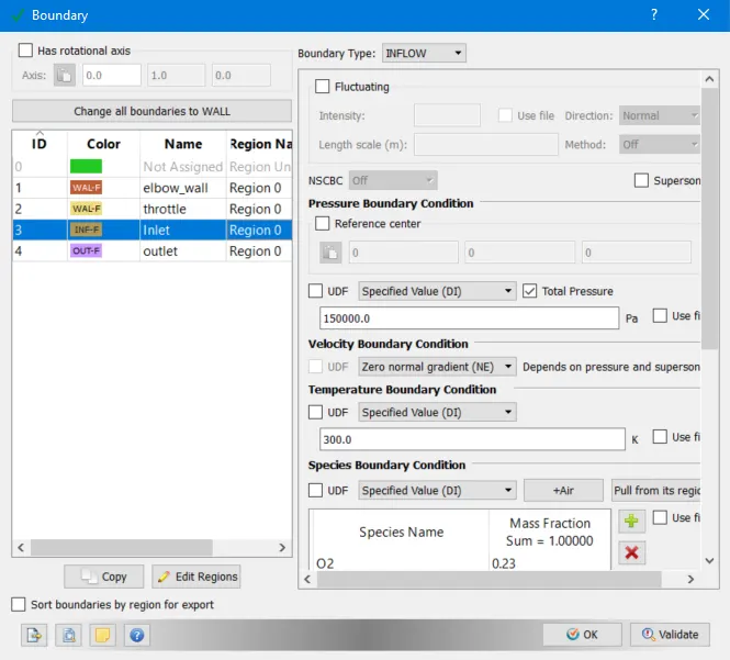
- Boundary conditions
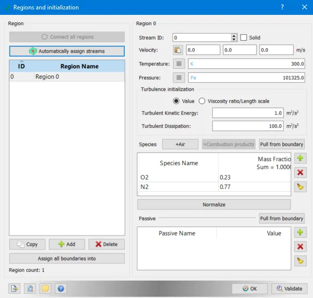
- Regions/Initializations
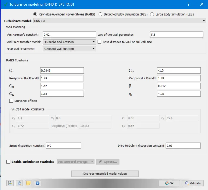
- Turbulence Model --> RNG K-e model
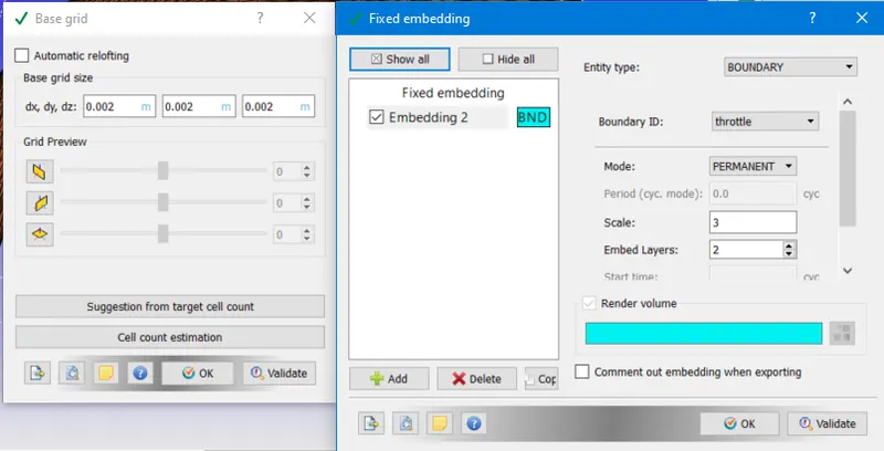
- Base Grid and Fixed embedding
Results
- Mesh
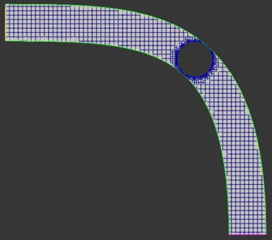
Throttle Body (Fixed embedding refinment)
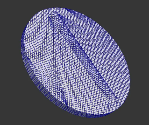
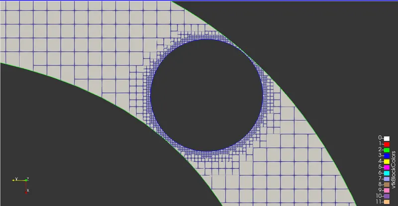
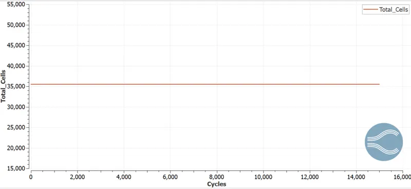
--> Grid size of 2 mm is used globally. Fixed embedding provides 2 layers of mesh refinment on the throttle wall. We can also see that converge uses a cut cell method to mesh the shapes of the geometry.
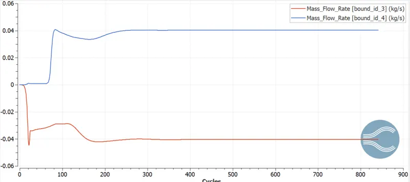
- Mass flow rates
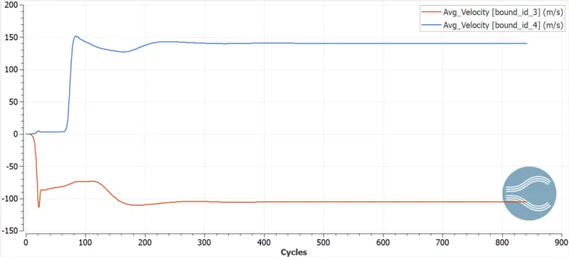
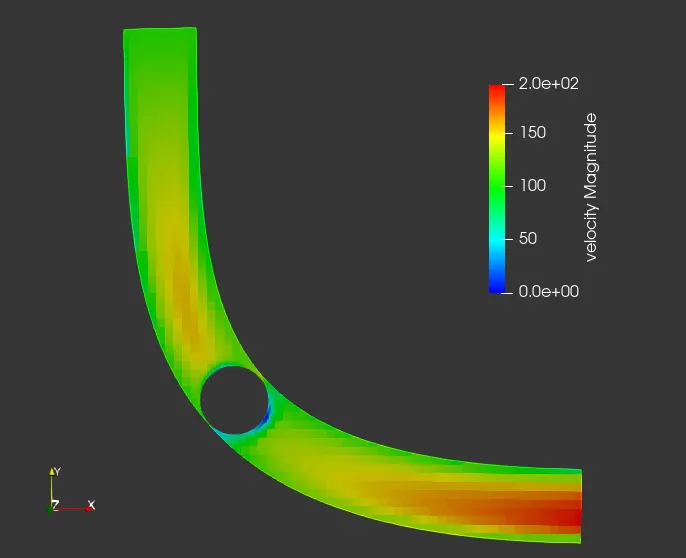
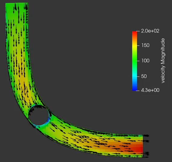
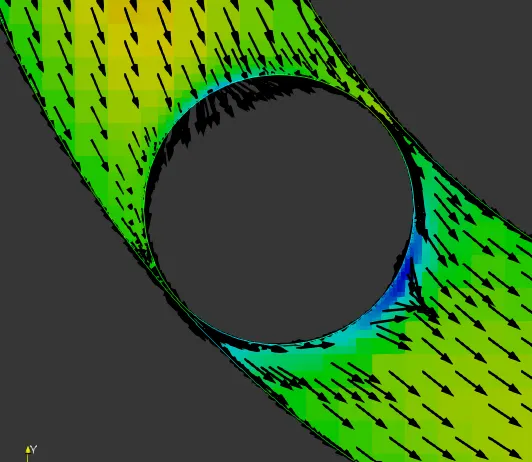
- Velocity plots/contours
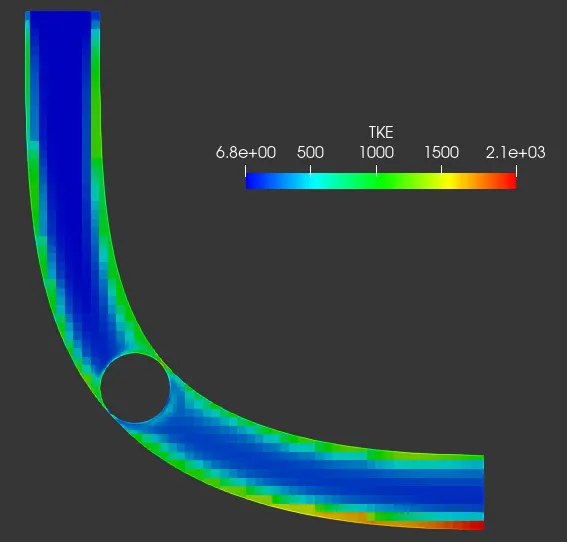
- Turbulent kinetic Energy
- Pressure
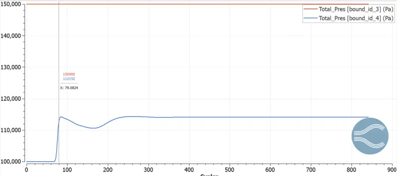
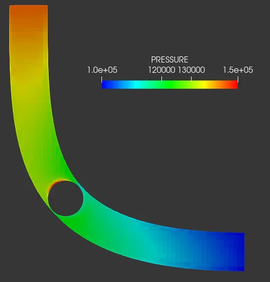
Throttle body (Pressure Contour)
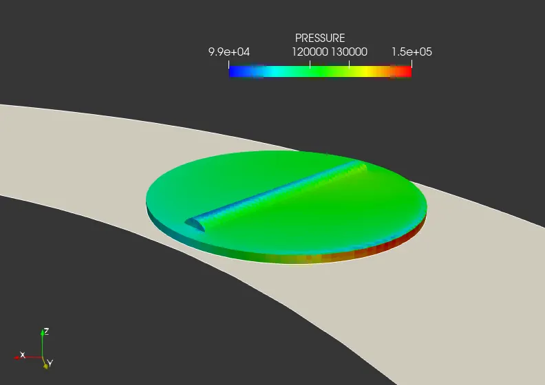
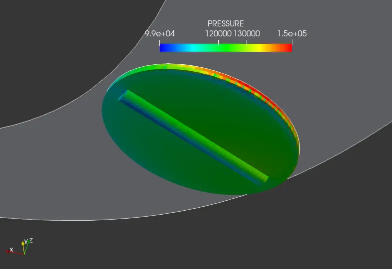
Conclusions
- A steady state simulation is run for flow over throttle body using Converge CFD.
- Velocity contours pressure plots are post processed and documented.
- regions of flow recirculations max. velocity and pressure field can be identified with this simulation.
- Flow over throttle body is successfully analysed.