Week 4.1: Project - Steady state simulation of flow over a throttle body
Aim : Simulation of flow over throttle body using converge Cfd and post processing using paraview.
Objectives :
- Set up and run the steady state simulation for flow over throttle body.
- Post process the results and show pressure and velocity contours.
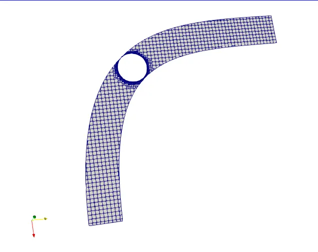
- Show the mesh (i.e surface with edges)
- Show the plots for pressure, velocity, mass flow rate and total cell count.
- Create an animation in which it throttle movement should be visible.
Introduction:
Steady state - The process in which the simulation parameters doesn't change with time is known as steady state process.
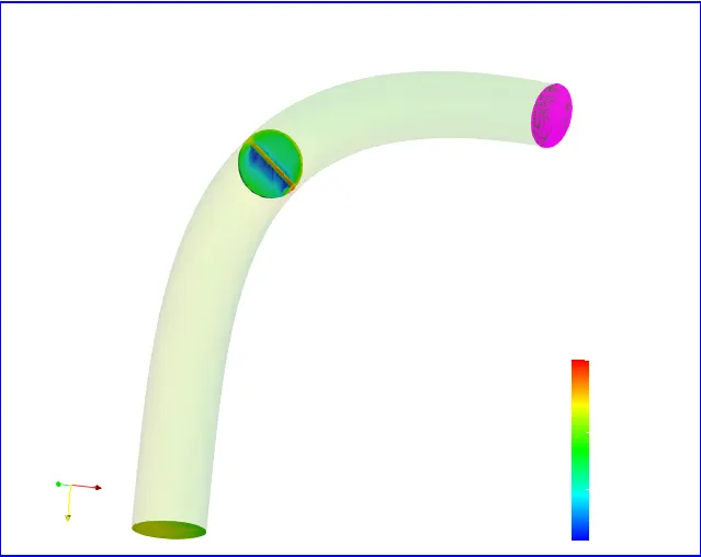
Throttle body - It is a elbow body which contain throttle inside.
In steady state simulation we keep the throttle body stationary and fixed, and apply parameter such as inlet velocity, pressure and temperature any one among them which in turn gives a value of other parameters.
Elbow body:
Case setup:
- Select the required dialog box for all the parameters that appear in the case of the setup tree, once selected we can start adding on the values i.e.
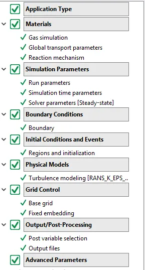
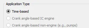
- The first parameter is application type which should be selected as à time base (since we are simulating steady-state simulation)
- The next parameters are materials in which we should check the following dialog boxes , gas simulation, global transport properties, and reaction mechanism. For gas simulation, and transport properties we should keep the properties as same.
- Now we add values for simulation parameters in which we should check the following dialog boxes run parameter, simulation time parameters, and solver parameters.
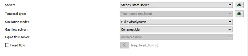
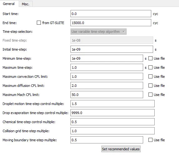
- In simulation parameters, we can control start time-end time and time steps also CFL number which actually controls the stability of any solution.
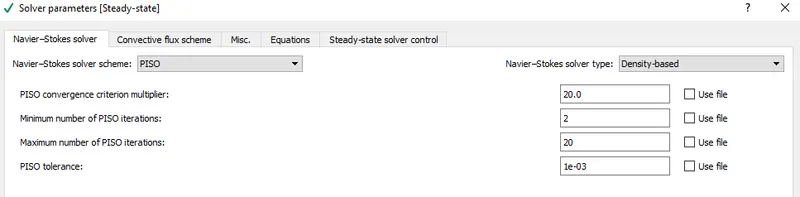
- In solver parameters, we will specify the solver scheme and can make choice in b/w density-based or pressure-based solver type.
- It’s Turn to add boundary condition the four boundaries are being named as an inflow (inlet), Outflow (outlet), elbow wall, throttle body.
- Now it is a turn to provide a volumetric region on which initial conditions can be applied which can be set inside initial conditions and events in regions and initialization.
The pressure value for the volumetric region is 1 bar and temperature 300K
- We will be using turbulence modelling for this case.
- The next step is to add a grid which can be done in Grid control à base grid.
The fixed embedding is used when we require a finer mesh elements at boundary of the geometry to get a accurate results at the boundaries.
We will apply finer mesh size at throttle boundary to get minimum of 2 to 3 cells at its boundary, the scaling factor should be taken as 3, and the no of embed layers are 2.
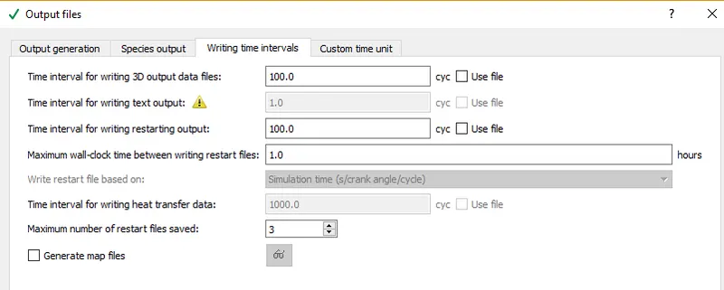
- The final step in case set-up is Output/Post-processing in this section we can define the time interval for writing a 3D – output file such that we can get a maximum number of post-processed files for smooth animation.
RESULTS:
Mesh at the boundary of the throttle:
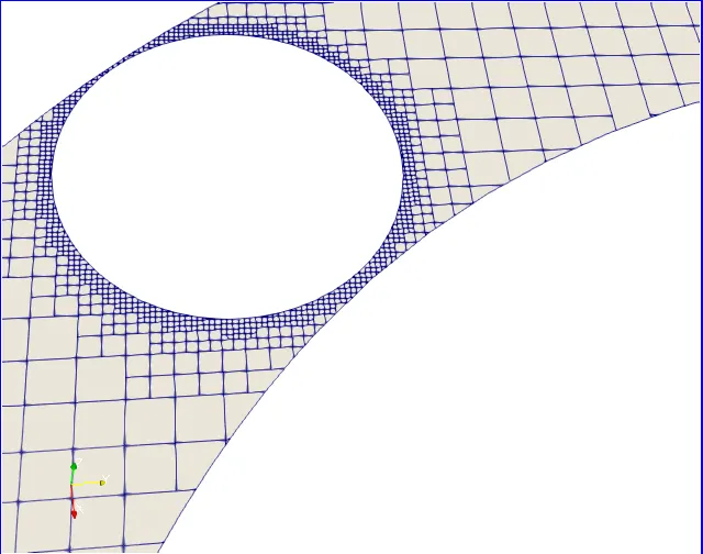
The mesh size variation can be seen from above figure which we have set using fixed embedding.
Mesh distribution over whole elbow body:
Glyph:
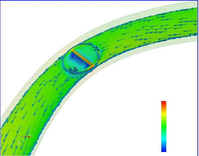
Above figure illustrate the direction of vector which confirms the direction of flow from inlet to outlet and variation of vector at throttle.
Velocity Contour:
Pressure Contour:
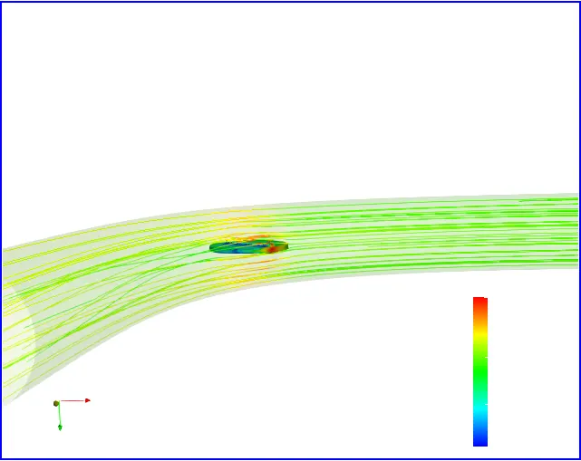
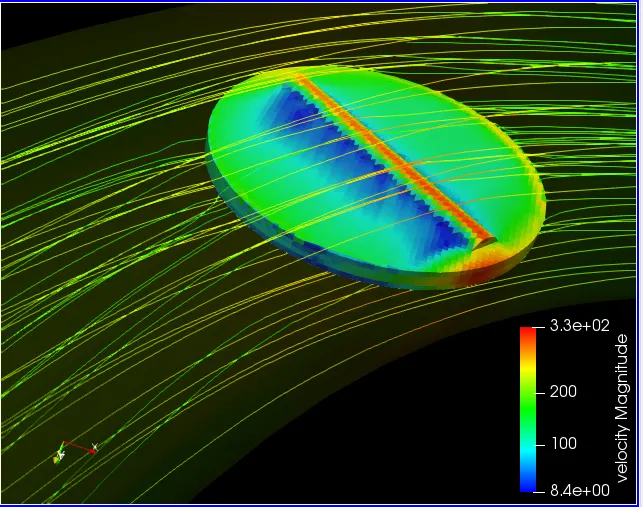
Velocity Steamlines:
Velocity plot at inlet and outlet:

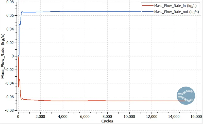
Mass flow rate plot at inlet and outlet:
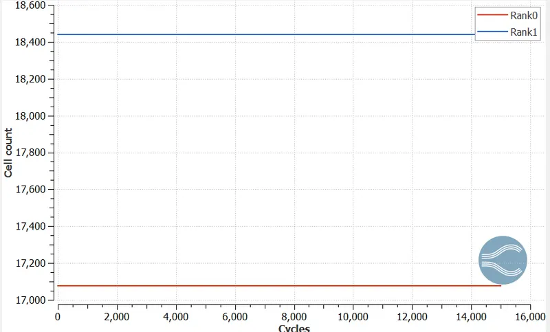
Cell count:
Conclusion:
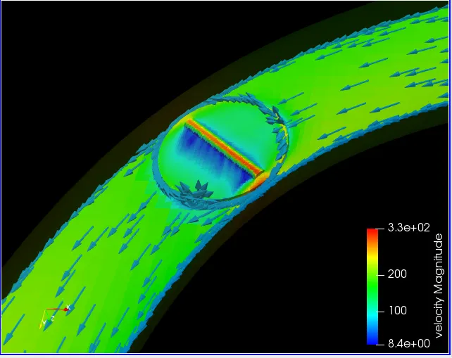
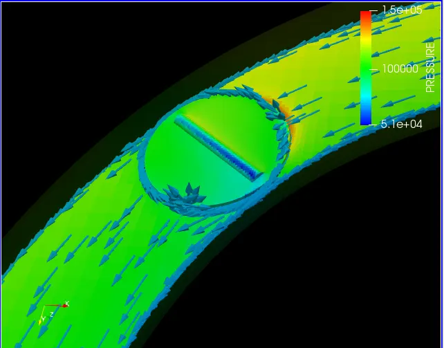
- There is high pressure region when air strikes the throttle during flow which can be seen by red zone.
- There is separation of flow at certain areas which can be seen by blue zone.
- Flow also occurs from the sides of the throttle since there is gap.
- Mass flow rate, velocity converges after 12000 time steps.