Week 4.1: Project Steady state simulation of flow over a throttle body
Aim: To set up a steady-state simulation of flow over a throttle body.
Procedure:
To create / import geometry:
1) click on file > import > import STL then select the path of .STL file to be imported and click import.
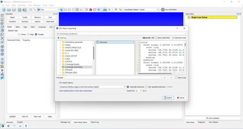
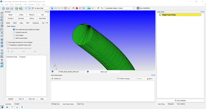
2) After importing geometry delete the thickness and seal the ends. To delete faces Repair>Delete>Select triangles and click apply. To patch edges Create>Patch>free edge loop select the open edge and click apply.
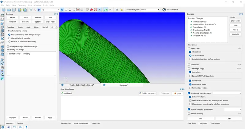
3) click on diagnosis to check for any errors. If all the normals are pointing inside the geometry then we can move ahead if not we can flip the orientation of normals inside using Transform > Normals > Propogate change from single triangle select a triangle and hit apply.
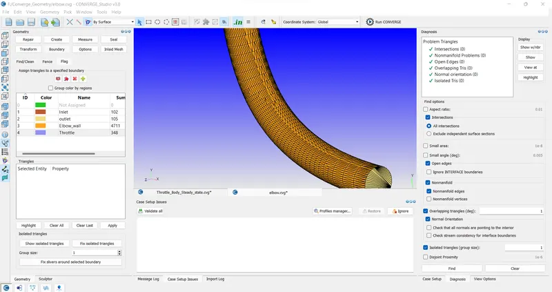
4) Next step is the boundary creation.
Case Set up:
1) Click on begin case set up to start case set up select application type as time-based and Predefined mixture as the air. Uncheck reaction mechanism and check species.
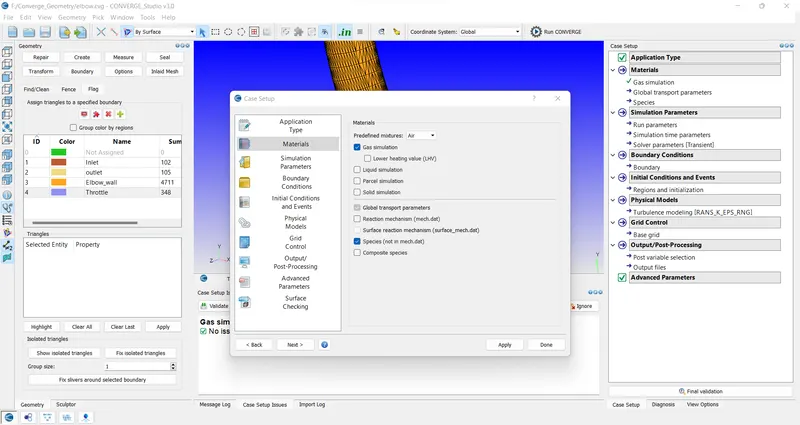
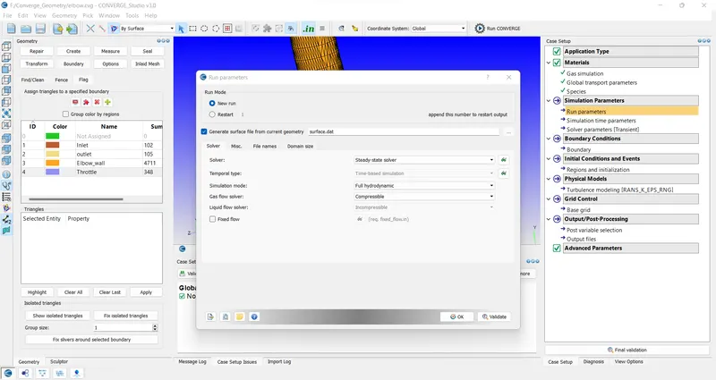
2) Do not change global transport properties and add species N2 and O2 in the species section, In run parameters select solver type to be the steady-state solver.
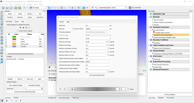
3) In simulation time parameters start time is 0 cycles and the end time to be 15000 cycles initial time step is 1e-9 secs, the minimum time step is 1e-9 sec and the max time step is 1 sec.
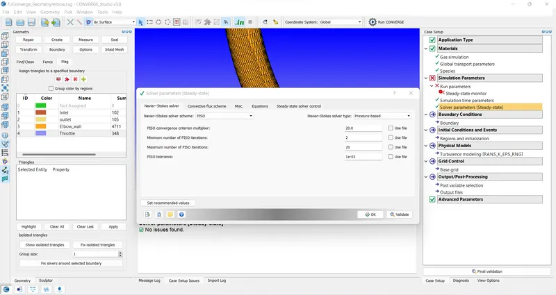
4) In solver parameters select Navier-stokes solver type as pressure-based solver.
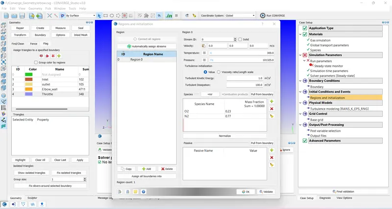
5) Add a new region and include air as species in it keeping other default values as it is.
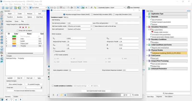
6)In the Physical model select RNG k-`epsilon` keeping other values as default.
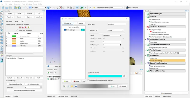
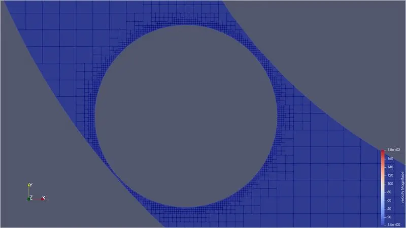
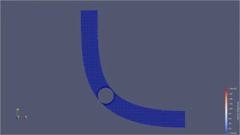
7) The next step is to create a mesh size. Click on grid control then check on fixed embedding. In embedding select entity type as boundary and boundary ID as Throttle. Select Mode to be permanent and scale as 3 and layer to be 2.
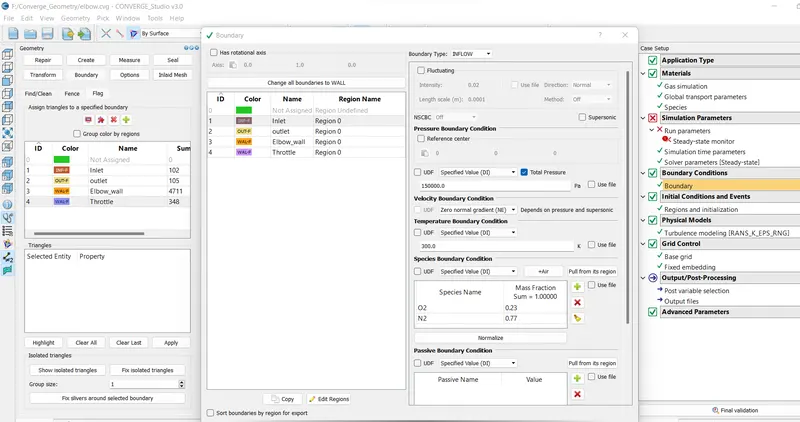
8) Now we can edit Boundary parameters: Inlet - Inflow P= 1.5e5Pa T=300K Species: Air
Outlet - Outflow P=1e5Pa T=300K Backflow species: Air
Elbow_Walls, Throttle- Walls and select law of the wall.
9) Do not change anything in Output files and post variable selection. Click on final validation to check for any errors.
reduce mesh size to avoid memory overflow error.
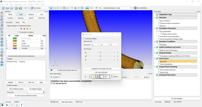
10) input files are ready for processing.
Processing input files:
1) Click on file > export > input files
2) Copy and paste licence.lic and mpiexec.exe file in the folder of input files
3) Open Cygwin browse to input files folder
4) Enter the following commands
mpiexec.exe -n 6 “C:\Program Files\Convergent_Science\CONVERGE\3.0.16\bin\intelmpi\converge.exe” restricted
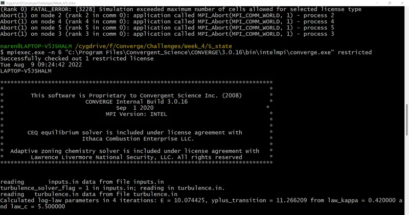
5) After completion of the process.
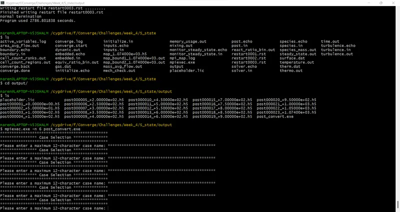
6) Copy and paste the post_convert file in the output folder in the cygwin Enter command
mpiexec.exe -n 6 post_convert
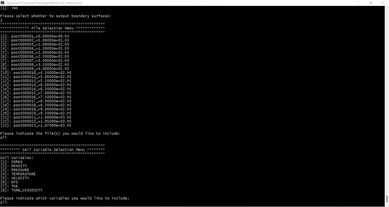
7) Enter the Name for the case selection
8) Enter file type to export as Paraview VTK in-line binary format
9) Select yes to put boundary surface output
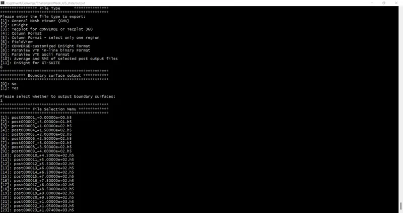
10) Include all file for post processing
11) Include all cell variables
Post-processing of files:
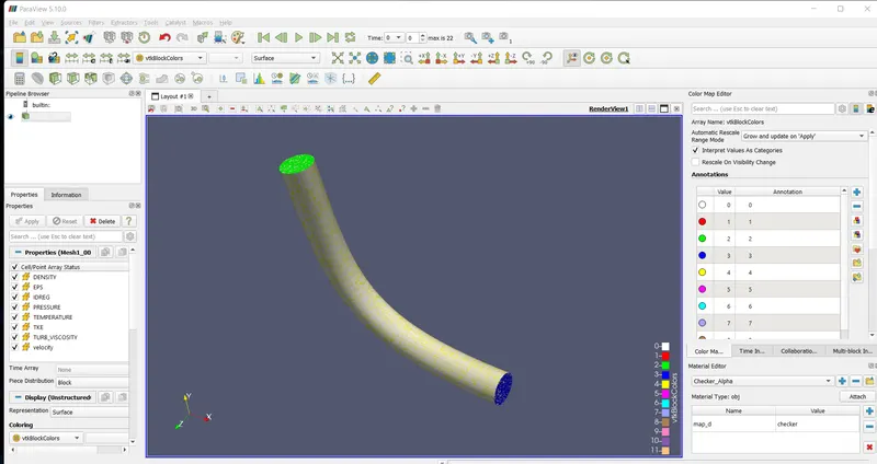
1) Open Paraview for post-processing and open a folder named output and open the file with extension .vtm and click apply.
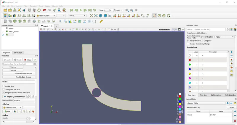
2) Click on slice and along Z normal uncheck triangulate slice and show plane.
3) Select velocity click play and check on visibility change.
Results:
Mesh-
Velocity contour:
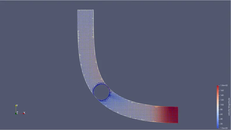
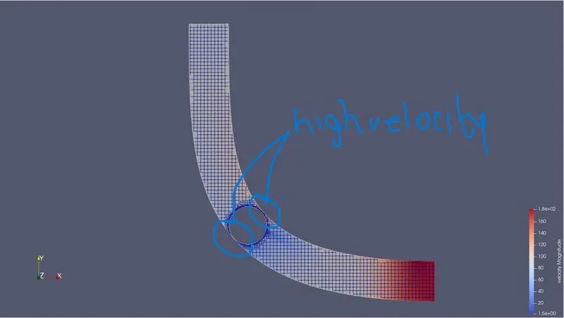
velocity in the region near the throttle body is high as the region is narrow so the area is small so according to Bernoulli's principle velocity is high. Flow separation occurs after flow passes through the narrow region as we can see velocity is reduced after passing over throttle body.
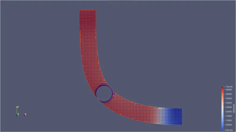
Pressure Contour:
Velocity:
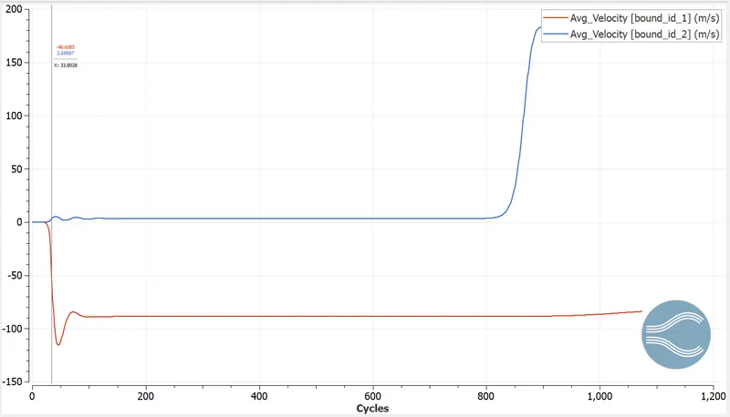
Pressure:
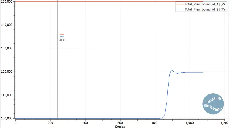
Mass Flow rate:
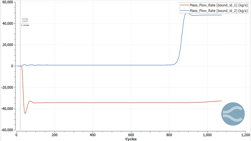
Total cell count:
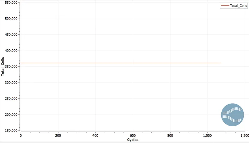
YouTube:
Velocity: https://youtu.be/H5n9lRNCTBE
Pressure: https://youtu.be/11WzoiudA9I