Simulation of Sheet-Metal Bending using Ansys Workbench
OBJECTIVE
- To punch the sheet metal using different non-linear materials viz. aluminum alloy 1199, copper alloy, and magnesium alloy, and find out the equivalent stress, equivalent elastic strain, and total deformation developed in it.
- To change the coefficient of friction from 0.1 to 0.19, and compare the results.
- To refine the mesh of the sheet metal and compare the result.
PROCEDURE
The simulation seems to be static non-linear, therefore, it had to solve using the Static Structural module of Ansys. The punch, sheet, and die models are shown in the figure below. Next, the material had to define before proceeding further. Using Engineering data, all the three required materials viz. aluminum alloy 1199, copper alloy, and magnesium alloy were imported.
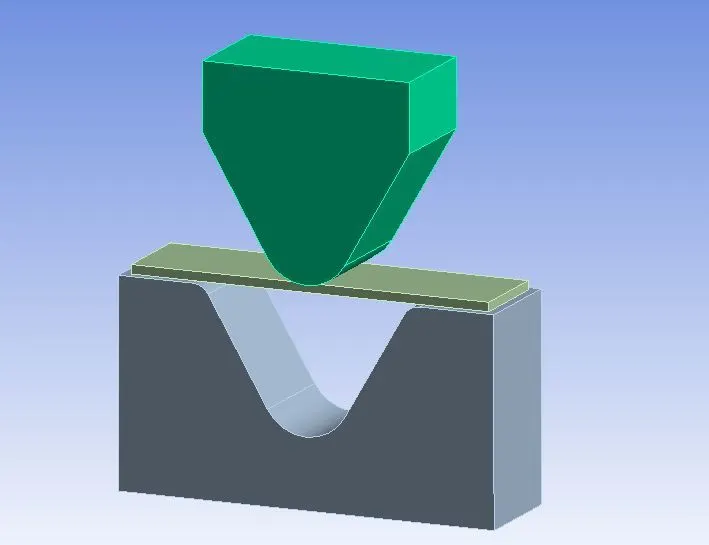
Figure 1: Punch, sheet, and die model in Ansys GUI.
The Mesh section of the Static Structural module was opened. In that, firstly, the material of the sheet was changed to Aluminum Alloy 1199 and set Parametric. The material of punch and die was kept as default i.e., Structural Steel.
Further, Ansys already detected the contact regions and therefore created contact cards for those. The automatically created contact cards were deleted, and two contact cards were created manually, for the frictional contact between the punch and the sheet, and the sheet and the die, respectively. In those cards, the behavior was set to Auto Asymmetric, and the formulation was set to Augmented Lagrange.
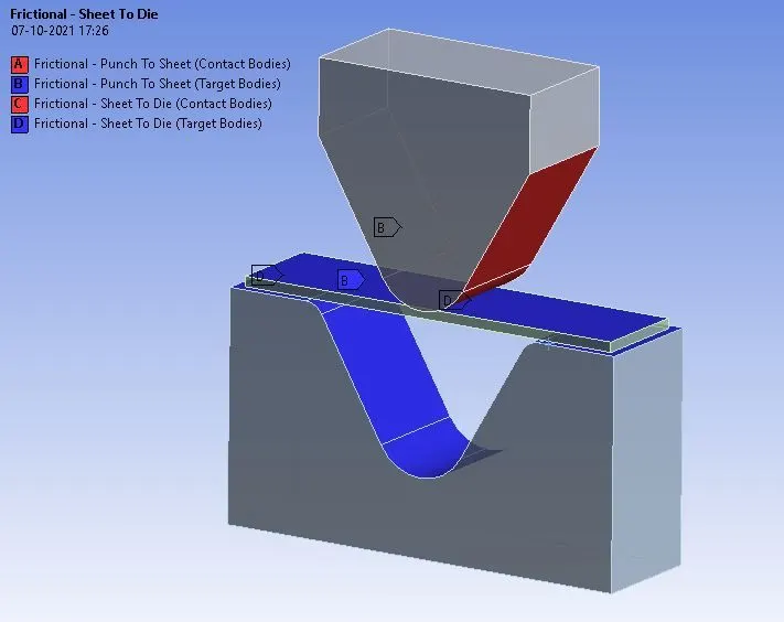
Figure 2: Frictional contact set between the punch and the sheet, and the sheet and the die.
After contact, the model had to mesh. For meshing, the element size for punch and die was set to 4 mm, and for sheet metal, it was set to 1 mm. Further, for the contacting surfaces of punch and die, the element size was set to 1 mm, i.e., face sizing was set to 1 mm. For meshing the sheet metal, tetrahedron elements were chosen.
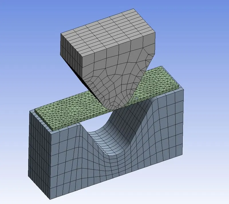
Figure 3: Meshing of the model.
The simulation was solved in 10 steps. For that, in Analysis Setting, the number was steps was increased to 10. The large deflection was turned on. Then, in the simulation, the bend the sheet metal, the punch should move in a vertically downward direction. Therefore, the Displacement constraint was given to the punch in tabular form, as shown below.
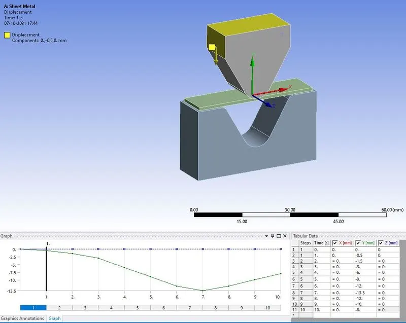
Figure 4: Displacement is given to the punch.
While bending, the sheet should not move in the lateral direction, therefore, its displacement was constrained in the z-axis, as shown below.
Further, when the sheet metal is punched, after that the punch withdraws. After the punch withdrawal, the die should also withdraw. Therefore, such constrained displacement motion was given to die.
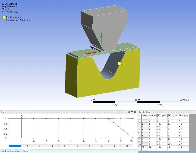
Figure 5: Constrained motion to the die.
Now, as the result, equivalent stress, equivalent elastic strain, and total deformation had to check. Therefore, it was requested in the output and it was set to Parametric, for getting the results for the other two cases.
Once done with this, in the Parameter section of Static Structural, two other cases were also set to solve. Those were, in which, the material of sheet metal was changed to copper alloy, and magnesium alloy, as shown in the figure below.
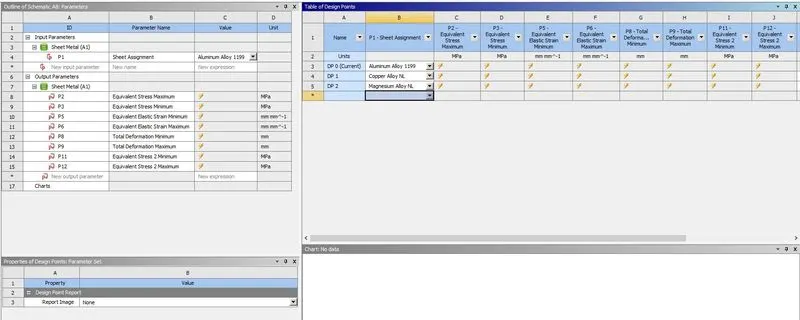
Figure 6: The three cases solved using a single platform.
In the above Parameters section, P2 and P3 are the maximum and minimum equivalent (Von-Mises) stress of the model, respectively. P5 and P6 are the maximum and minimum equivalent elastic strains developed in the model, respectively. P8 and P9 are the maximum and minimum total deformation developed in the model, respectively. And, P11 and P12 are the minima, and maximum equivalent stresses developed in the sheet metal only, respectively.
After solving the problem following results were collected from the software.
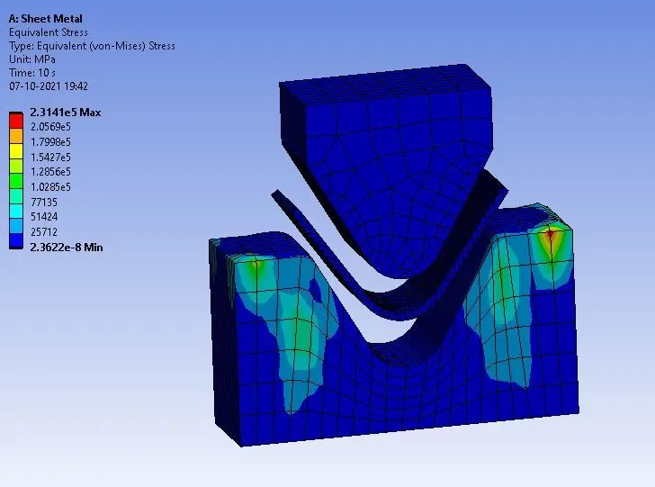
Figure 7: Equivalent Von-Mises Stress developed in the model.
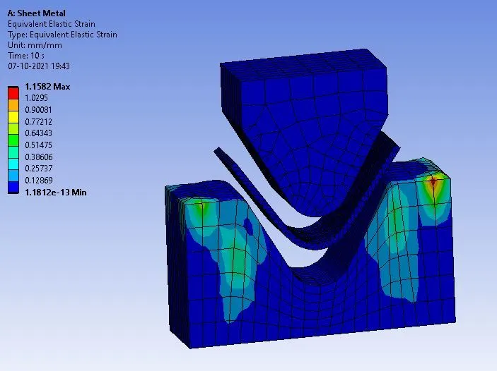
Figure 8: Equivalent Elastic Strain developed in the model.
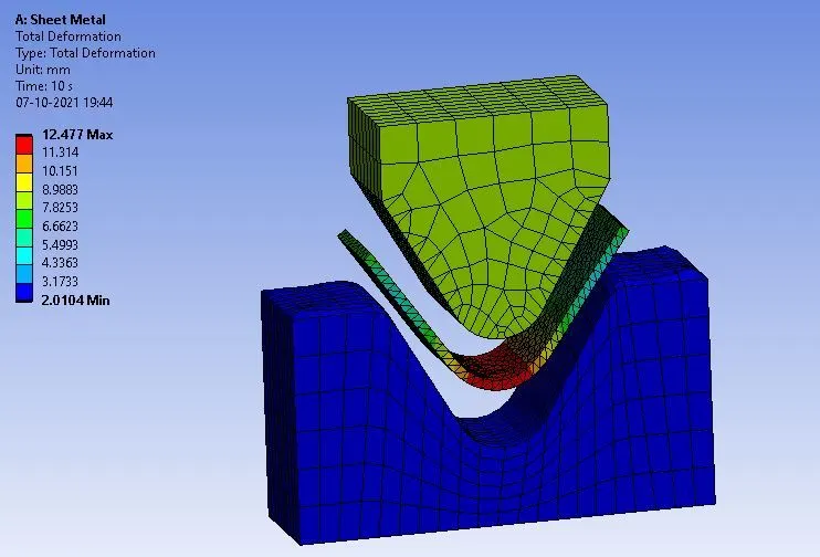
Figure 9: Total deformation developed in the model.
From fig. 7, 8, and 9, stresses, strains, and deformation developed in the model during the bending of the sheet metal can be observed. The stresses developed in the model are quite high which seems not to be realistic. But that stress developed is in the die part. Stress developed in the sheet metal is shown in the figure below.
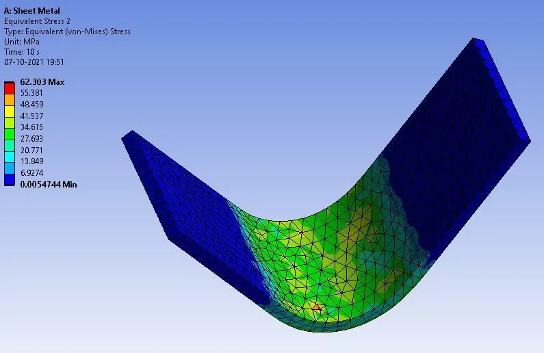
Figure 10: Stresses developed in the sheet metal.
Now, the maximum developed stress in the sheet metal can be observed equally to 62.303 MPa. These results using different material is shown below.
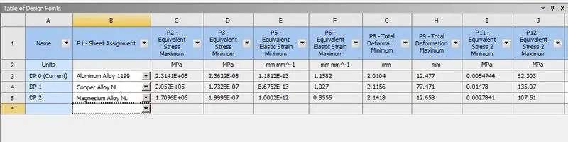
Figure 11: Equivalent stress, equivalent elastic strain, total deformation in the model, and equivalent stress in sheet metal.
Fig. 11 shows the results for the 3 cases. Out of all the results, section P12 results is quite appreciable. It is a section of results for the maximum stresses developed in the sheet metal. When the aluminum alloy 1199 was used the induced stress was only 62.303 MPa, but in the case of copper alloy and magnesium alloy it was 135.07 MPa, and 107.51 MPa respectively. It shows the formability of the aluminum material.
The second objective was to check the results by changing the coefficient of friction to 0.19. The below figures shows the equivalent stress and equivalent strain induced in the sheet metal when the coefficient of friction was increased.
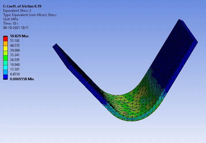
Figure 12: Equivalent stress induced in the sheet metal, in case of coefficient of friction of 0.19.
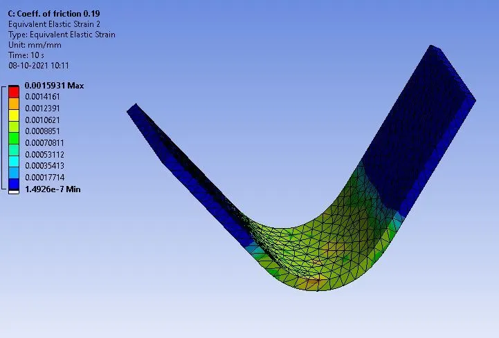
Figure 13: Equivalent strain induced in the sheet metal, in case of coefficient of friction of 0.19.
From fig. 12 and 13, it can be observed that the maximum stress in the sheet metal reduced slightly from 62.303 MPa to 59.829 MPa, which is not a significant change in value to consider. It shows that increasing the coefficient of friction had not had affected the stresses developed. This can be because of the limited movement of the sheet metal under the applied load.
The last objective was to check the results of stress and strain induced in the sheet metal by refining the mesh. So, another Structural Steel module was opened, and the same setup was prepared as earlier. But in here, the element size of sheet metal was reduced from 1 mm to 0.8 mm. Therefore, earlier the total number of nodes was 17973 and the total number of elements was 6255, and in this case, the total number of nodes was increased to 24226, and the total number of elements was increased to 10089. The results of this case are shown below.
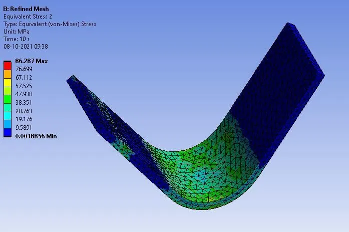
Figure 14: Equivalent (Von-Mises) Stress in the sheet metal when the mesh was refined.
Comparing fig. 11, and 14, it can be observed that there is a significant change in the stresses induced in the sheet metal. In the case of mesh with a 1 mm element size, the maximum stress induced was 62.303 MPa, and in the case of mesh with element size 0.8 MPa, the maximum stress induced was 86.287 MPa. It means in earlier cases there was a difference of 55% of the maximum stress from yield strength, and now it is 38%. Thus, after the removal of the load from the sheet, the high stresses remain closer to the yield point.
CONCLUSION
In this work, the sheet metal had to bend, and the results like stress, strains developed in the sheet metal had to check. The work was accomplished using three different objectives. In the first objective, the stresses and other parameters were checked for three different materials of sheet metal. From which it was found that Aluminium Alloy 1199 should be the preferred material out of aluminum alloy 1199, copper alloy, and magnesium alloy. Aluminum alloy has good formability. In the second objective, the coefficient of friction between contact surfaces was increased from 0.1 to 0.19. But it had no significant effect on the result. The reason can be the limited movement of sheet metal. In the third objective, the mesh of the sheet metal was refined from the element size of 1 mm to 0.8 mm, and its equivalent stress changed from 62.303 MPa to 86.287 MPa. This shows how much mesh density affects the results.