Sheet metal Bending Analysis
AIM:
- To perform Static Structural analysis on Sheet metal bending by applying different materials to find the stress, deformations results and compare them in ANSYS Workbench.
OBJECTIVES OF THE PROJECT:
- To define material for the punch, die and the sheet.
- To define contact faces for the punch, die and the sheet.
- To define translational movement of punch and the die.
- To constrain the movement of sheet in the Z direction.
- To perform mesh on the punch, die and the sheet.
- To define face sizing for contact faces.
- To define body sizing for the sheet.
- To evaluate the maximum stress, strain and deformation.
PROCEDURE:
- Case 1 (Aluminium Alloy 1199) -
- OPEN > WORKBENCH > NEW PROJECT > STATIC STRUCTURAL.
- Rename the project as Case_1_Al_1199.
- This will define static structural project.
- Now, go to ENGINEERING DATA > EDIT > GENERAL MATERIALS > ALLUMINIUM ALLOY NL > ADD.
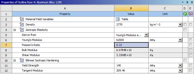
- Then, create duplicate of the aluminium alloy non-linear and name it as Aluminium alloy 1199.
- Change the values as below.
- Go to GEOMETRY > IMPORT > BROWSE > Al_SHEET_BENDING.STP.
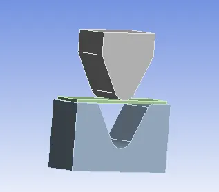
- This will import the sheet metal bending geometry.
- Then, DOUBLE CLICK ON MODEL. This will open the mechanical module.
- Rename the parts as Punch, die and sheet respectively.
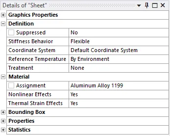
- Assign material as Aluminium alloy 1199 to the sheet component.
- Go to CONNECTIONS > CONTACTS > DELETE ALL CONTACTS.
- Then, CONNECTIONS > CONTACTS > INSERT > MANUAL CONTACT REGION > CONTACT FACES > TARGET FACES > TYPE = FRICTIONAL > FRICTIONAL COEFFICIENT = 0.1 > BEHAVIOUR > AUTO ASSYMETRIC > FORMULATION = AUGMENTED LAGRANGE > NORMAL STIFFNESS > FACTOR > 0.1 > INTERFACE TREATMENT > ADD OFFSET, RAMPED EFFECTS.
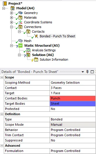
- This contact is defined between the punch and the sheet.
- Similarly, CONNECTIONS > INSERT > MANUAL CONTACT REGION > CONTACT FACES > TARGET FACES > TYPE = FRICTIONAL > FRICTIONAL COEFFICIENT = 0.1 > BEHAVIOUR > AUTO ASSYMETRIC > FORMULATION = AUGMENTED LAGRANGE > NORMAL STIFNESS > FACTOR > 0.1 > INTERFACE TREATMENT > ADD OFFSET, RAMPED EFFECTS.
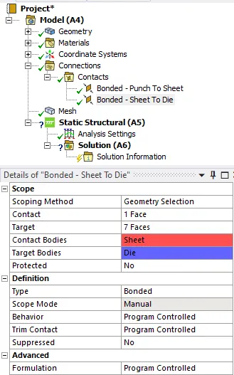
- This contact is defined between the sheet and the die.
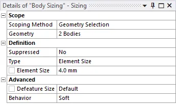
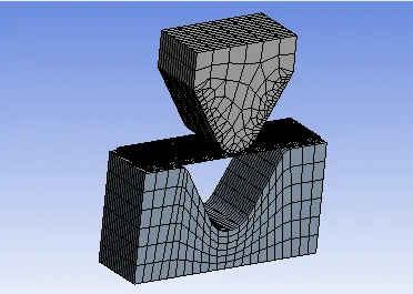
- Now, go to MESH > INSERT > SIZING > ELEMENT SIZE = 4MM > SCOPE > PUNCH AND DIE.
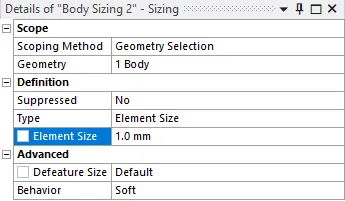
- Go to MESH > INSERT > SIZING > ELEMENT SIZE = 1MM > SCOPE > SHEET.
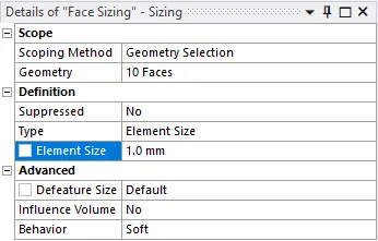
- Go to MESH > INSERT > SIZING > ELEMENT SIZE = 1MM > SCOPE > CONTACT FACES.
- Similarly, go to MESH > INSERT > METHOD > GEOMETRY = SHEET > METHOD > TETRAHEDRON.
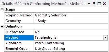
- Then GENERATE MESH.
- This will create mesh on the geometry according to the element sizing.
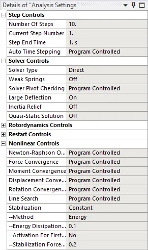
- Now, go to STATIC STRUCTURAL > ANALYSIS SETTINGS > NO OF STEPS = 10 > SOLVER TYPE = DIRECT > LARGE DEFELECTION = ON > NONLINEAR CONTROLS > STBILIZATION = CONSTANT > RATIO = 0.1.
- Then, go to STATIC STRUCTURAL > INSERT > DISPLACEMENT > MAGNITUDE = TABULAR DATA.
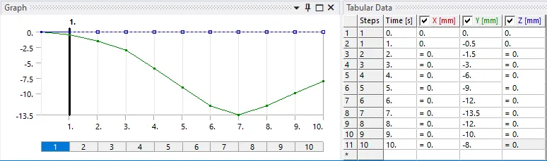
- This is for the Punch displacement.
- Similarly, STATIC STRUCTURAL > INSERT > DISPLACEMENT > MAGNITUDE = TABULAR DATA FOR Z.
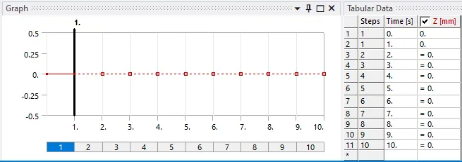
- This is for the constraining sheet displacement in Z direction.
- Similarly, STATIC STRUCTURAL > INSERT > DISPLACEMENT > MAGNITUDE = TABULAR DATA.
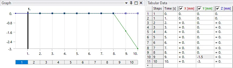
- This is for the Die displacement after punch.
- Go to SOLUTION > INSERT > STRESS > STRAIN > TOTAL DEFORMATION.
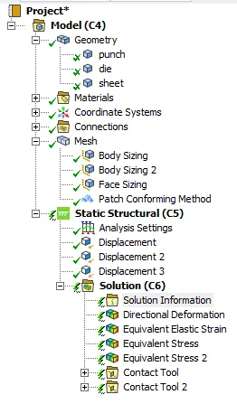
- Go to SOLUTION > SOLVE.
- Case 1 (Copper Alloy NL) -
- Create Duplicate project of Case_1_Al_1199 and rename it as Copper_alloy.
- Go to ENGINEERING DATA > EDIT > GENERAL MATERIALS > COPPER ALLOY NL > ADD.
- Open Mechanical module and assign Copper alloy material to the sheet geometry.
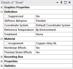
- Then, go to SOLUTION > SOLVE.
- Case 1 (Magnesium Alloy NL) -
- Create Duplicate project of Case_1_Al_1199 and rename I as Magnesium_alloy.
- Go to ENGINEERING DATA > EDIT > GENERAL MATERIALS > MAGNESIUM ALLOY NL > ADD.
- Open Mechanical module and assign Magnesium alloy material to the sheet geometry.
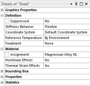
- Then, go to SOLUTION > SOLVE.
- Case 2 –
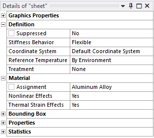
- For the second case, we have to assign Aluminium alloy material to the sheet geometry and friction coefficient as 0.9.
- Create Duplicate project of Case_1_Al_1199 and rename it as Al_alloy_0.19.
- Go to ENGINEERING DATA > EDIT > GENERAL MATERIAL > ALUMINIUM ALLOY > ADD.
- Then, open mechanical module and assign Aluminium alloy to the sheet geometry.
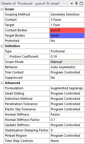
- Go to CONNECTIONS > CONTACTS > FRICTIONAL > FRICTIONAL COEFFICIENT = 0.19.
- Then, go to SOLUTION > SOLVE.
- Case 3 -
- For the third case, we have to refine the mesh on the plate.
- Create a Duplicate project of Case_1_Al_1199 and rename it as Case_3.
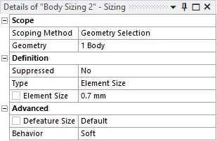
- Then open the mechanical module and go to MESH > PLATE > ELEMENT SIZE = 0.7MM > GENERATE MESH.
- Similarly, generate a mesh of 0.7mm for contact faces in the face sizing.
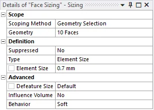
- This will generate a mesh of 0.7
- mm on the plate and the contact faces.
- Go to SOLUTION > SOLVE.
RESULTS:
| Case 1:Aluminium Alloy 1199 | Case 1: Copper alloy NL | Case 1: Magnesium alloy NL | |
| Strain | 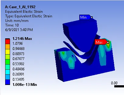 |
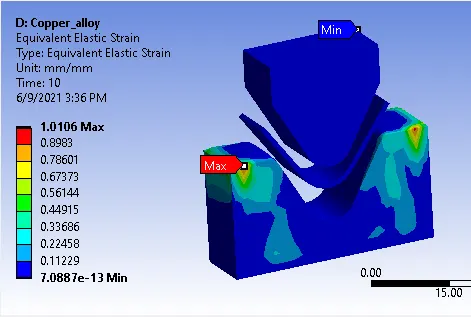 |
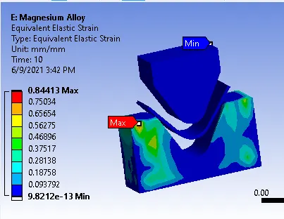 |
| Deformation | 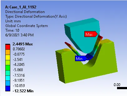 |
 |
 |
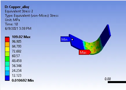
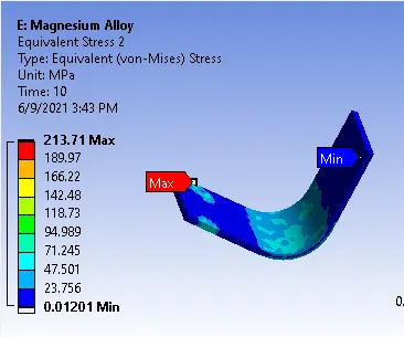
| Sheet stress | 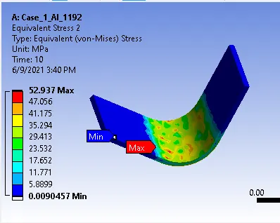 |
 |
 |
| Case 1: Aluminium Alloy 1199 | Case 2: Aluminium Alloy 1199 with FC = 0.19 | Case 3: Aluminium Alloy 1199 with plate mesh of 0.55mm | |
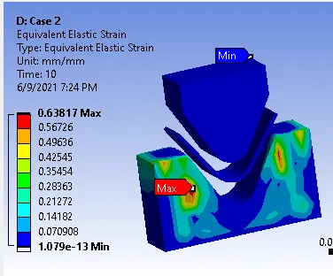
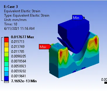
| Strain | |
 |
 |
| Deformation | |
 |
 |
| Sheet stress | |
 |
 |
COMPARISON TABLE:
| Strain (mm/mm) | Deformation (mm) | Sheet stress (MPa) | |
| Case 1:Aluminium Alloy 1199 | 1.2146 | 2.4495 | 52.937 |
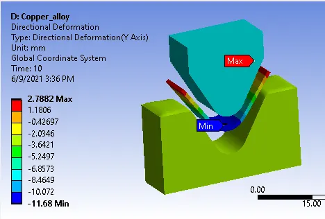
| Case 1: Copper alloy NL | 1.0106 | 2.7882 | 109.02 |
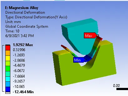
| Case 1: Magnesium alloy NL | 0.84413 | 1.9292 | 213.71 |
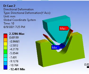
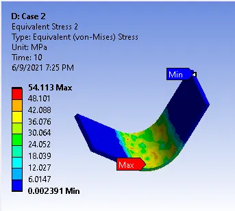
| Case 2: Al alloy, FC = 0.19 | 0.63817 | 2.3286 | 54.113 |
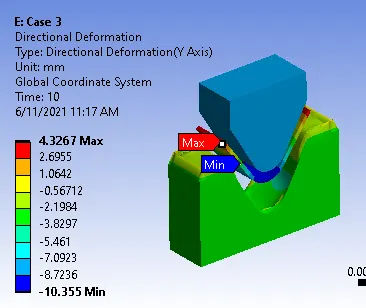
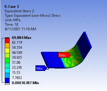
| Case 3: Al alloy, mesh = 0.7 | 0.01767 | 4.3267 | 69.884 |
- In Case 1:Aluminium Alloy 1199, the sheet stress is 52.937 i.e the material provides least resistance and is easy for bending. Also the strain rate is maximum and is caused in the die.
- In Case 1: Copper alloy NL, the sheet stress is greater than the Aluminium alloy 1199 i.e. the material properties change and thus the stress change. The strain reduces compared to previous case.
- In Case 1: Magnesium alloy NL, the sheet stress is maximum in all the cases. The strain rate is reduced.
- In Case 2: Aluminium alloy 0.19, the friction coefficient is increased to 0.19, hence as compared to the case 1 Aluminium alloy 1199, the stress is slightly increased in the sheet material and the strain rate is reduced.
- In Case 3: Refined Mesh, here the mesh on the contact faces and the sheet body is refined to 0.7mm, the sheet stress value is increased due to fine meshing. The deformation is also increased. This means the meshing of the sheet can be further reduced to obtain accurate results.
LEARNING OUTCOMES:
- To insert contact faces.
- To insert translational movement for the punch and die.
- To constrain the sheet in Z direction.
- To insert face and body sizing in meshing.
- To insert the desired output results.
CONCLUSION:
- Hence, by performing this project we conclude that the material properties such as Youngs Modulus and the Frictional coefficient affect in the stress values of the sheet geometry.
- The fine meshing of the sheet material will provide more accurate results.
- The Static Structural Analysis of Sheet Metal Bending is Performed and the results are obtained in ANSYS Workbench.