Week 3 Sheet metal Bending challenge
- Objective: To perform a static structural analysis on the given sheet metal for the given cases and compare the results.
Case 1: Aluminium Alloy 1199, Copper Alloy NL and Magnesium Alloy NL. Find out the Equivalent stress, Equivalent elastic strain and Total Deformation in Y direction and compare the results for the three
materials.
Case 2: With the material as Aluminium Alloy, change the friction coefficient to 0.19 and run the analysis as mentioned in Case 1. Compare the results with that in case 1.
Case 3: Refine the mesh on the plate such that it doesn't cross the academic limit. With Aluminium alloy as material, run the analysis as in Case 1 and compare the results.
-
Procedure:
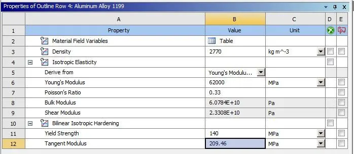
Open the static structural analysis system in the Project schematic. Rename it to Sheet_metal_bending. The material used for analysis are Aluminium Alloy 1199, Copper Alloy NL and Magnesium Alloy NL,
and Aluminium Alloy. These materials are added to the material library in Engineering Data. For Aluminium Alloy 1199, the material is added manually with the following properties:
Now proceed to import the Geometry. Import the Geometry and verify the geometry is proper and update and open the Mechanical module.
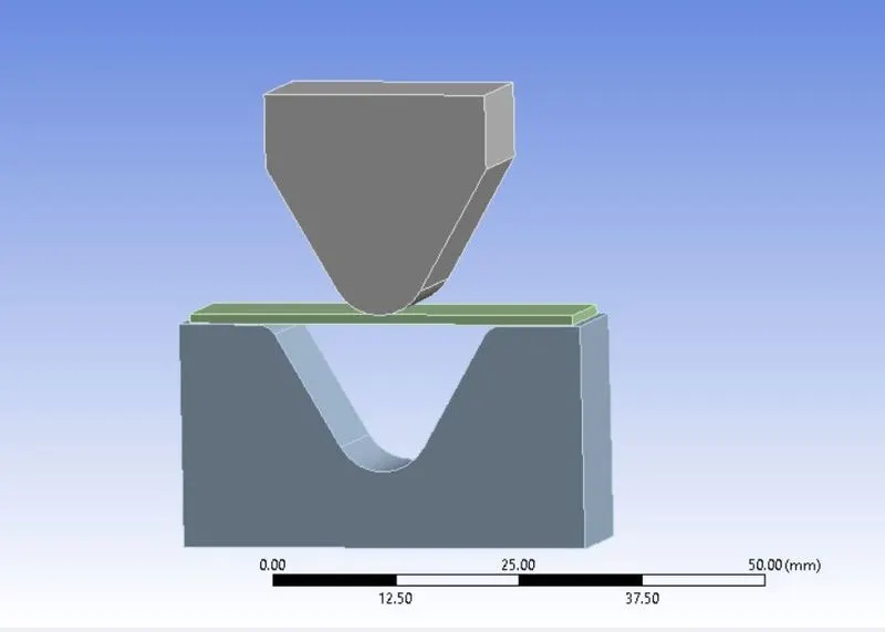
The Ansys automatic contact detection has detected some initial contact. Upon inspection, it is observed that some additional inputs should be defined in the detected contacts. Delete these contacts, and
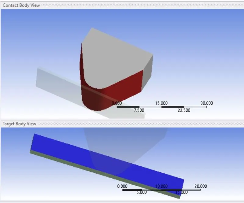
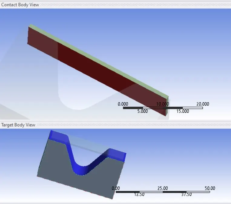
define the contacts manually. Go to Connections > Insert > Manual contact region. Define the contacts as shown below:
Contact between the punch and the sheet:
Contact between the sheet and the die:
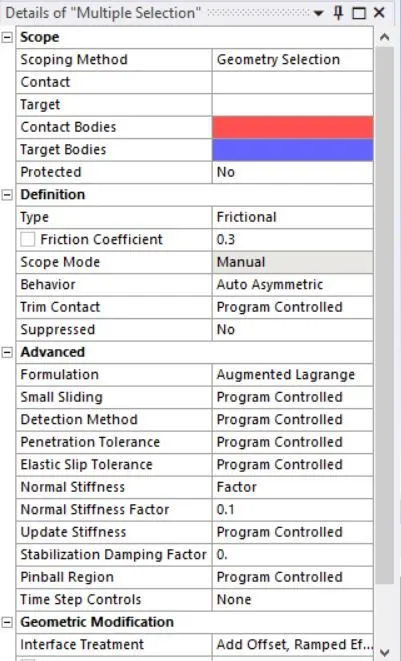
Following contact properties are used:
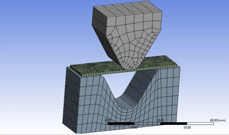
For meshing, face sizing of 4 mm is sued for the die and the punch. Similarly, for sheet, face sizing of 1 mm is used. Further, to get better results, the mesh in the contact regions is further refined by
introducing face sizing of 1 mm . Tetrahedron method is used for meshing in the contact regions and the geometry is meshed.
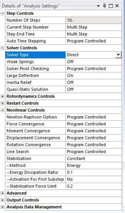
The displacements in the system are to be divided into 10 steps. Following analysis setting is used:
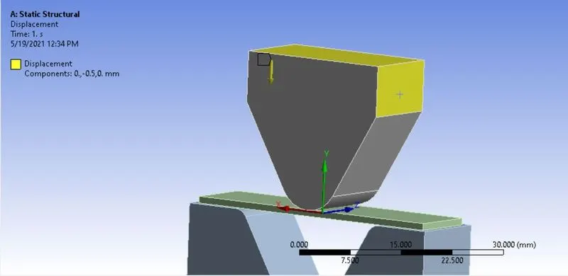
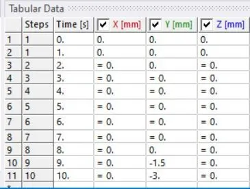
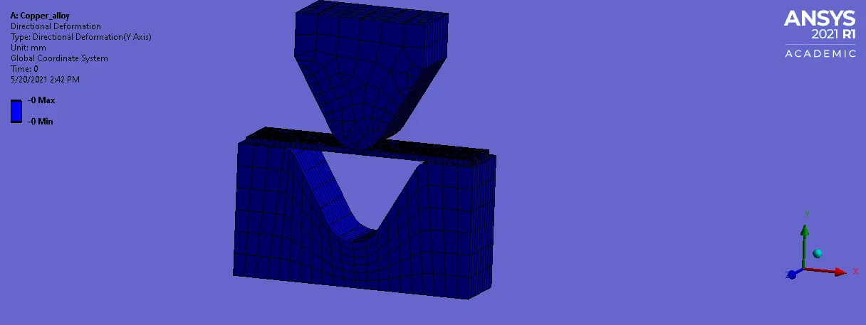
Now input the displacements. The punch is supposed to move downwards and after the end of the stroke, it is supposed to move backwards. This is achieved by providing the displacements in Y direction.
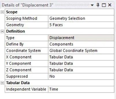
Go to Static structural > Insert > Displacement. Define the displacements by components as shown below:
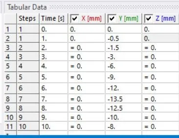
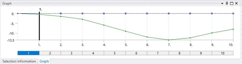
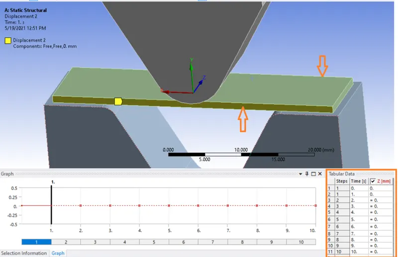
As indicated by the graph, the punch will have maximum downward displacement of 13.5 mm and after that it will retract. For the sheet, it is free to deform in the Y and X direction, but no displacement in
the Z axis is allowed. Go to Static structural > Insert > Displacement. Define the displacements by components. Set X and Y as free and for Z component, enter 0 as shown below:
For die, it should remain in place as the punch advances and retract once when the punch retracts.
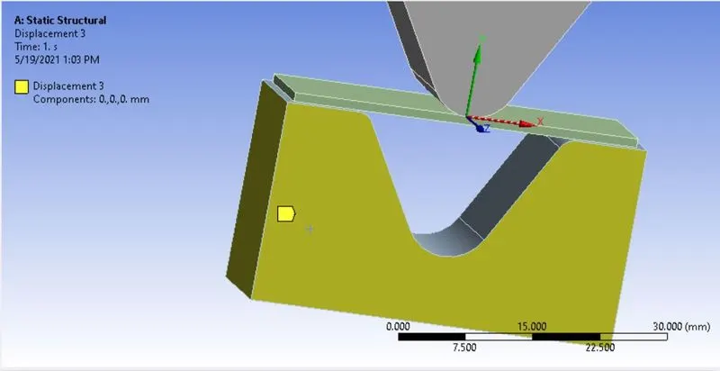
The case set up is now complete. Request the output parameters and run the simulation
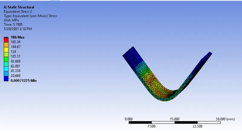
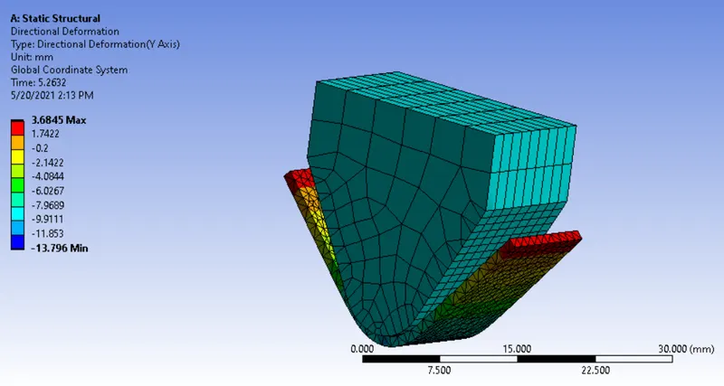
- Case 1: Aluminium Alloy 1199
Stress Contour:
Deformation:
strain contour:
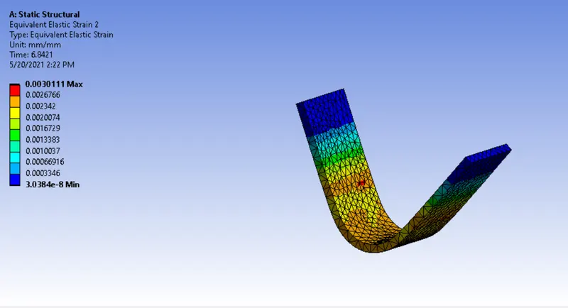
Magnesium Alloy:
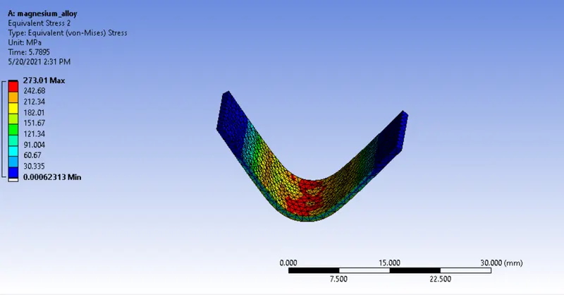
Stress Contour:
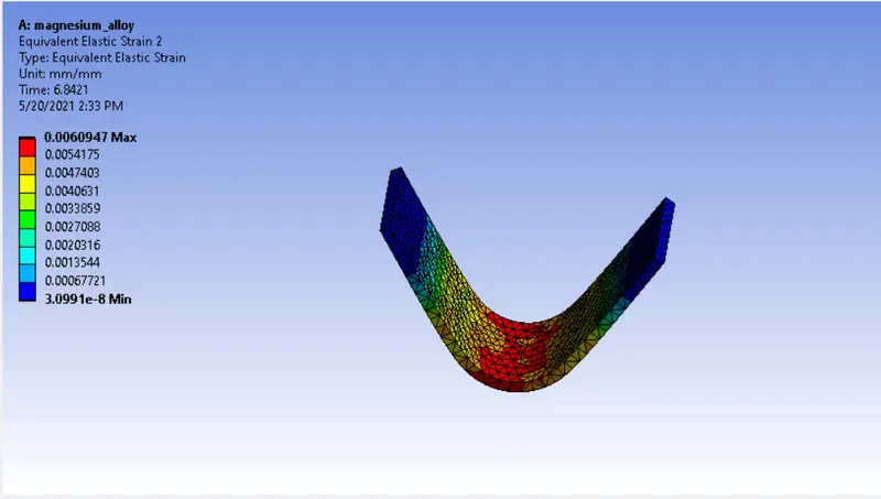
Strain contour:
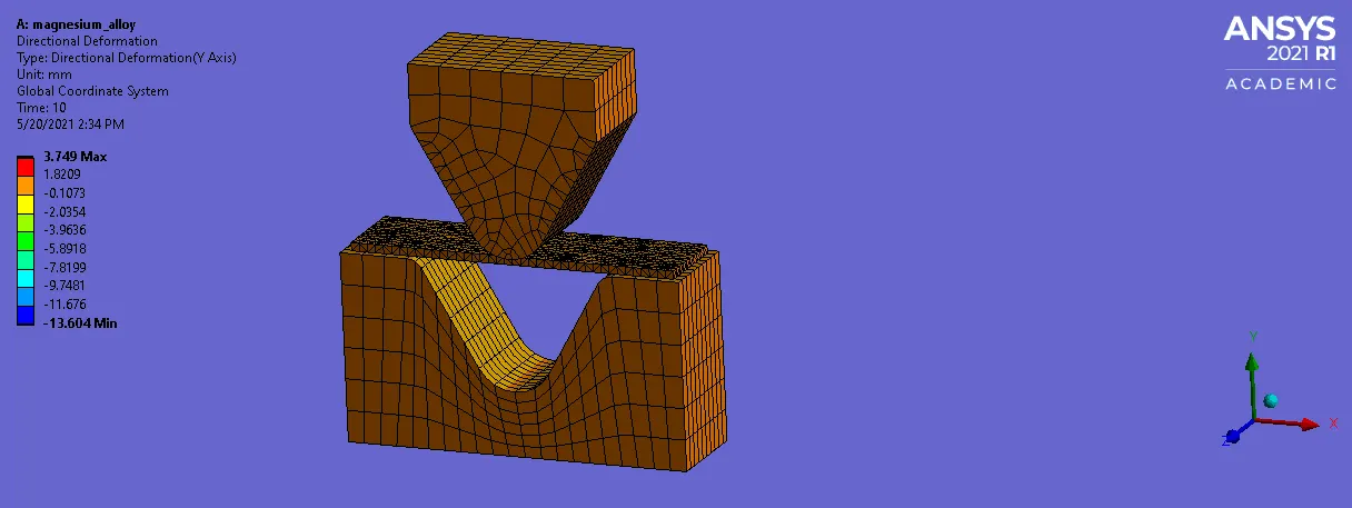
Deformation:
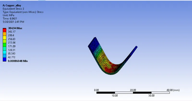
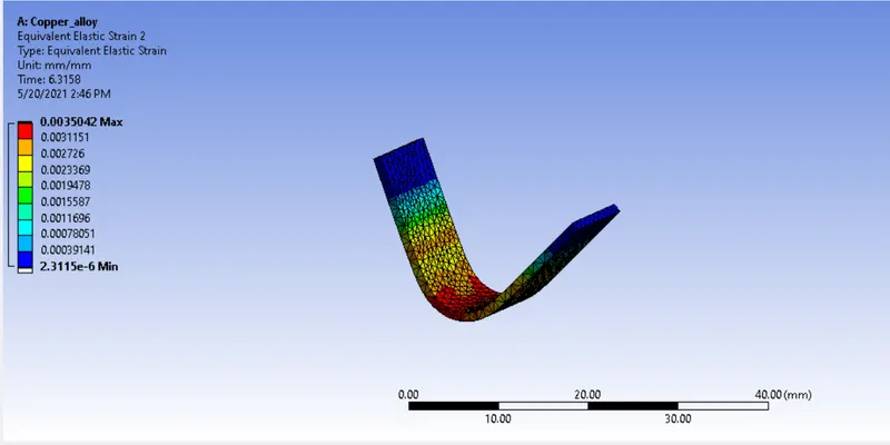
Copper Alloy:
Stress contour:
Deformation:
Strain contour:
- Compariosn of results:

The copper alloy has the highest Young's modulus and yield strength. It also has highest tangent modulus followed by magnesium alloy and aluminium alloy. Maximum stress is observed in the copper alloy,
followed by magnesium alloy and aluminium alloy. For displacement based boundary condtions, the stress will vary depending on material properties like Young's modulus,yield strength and tangent
modulus, which is mostly used to describe the stiffness of a material in the plastic range.
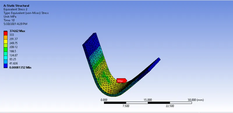
- Case 2: With the material as Aluminium Alloy, change the friction coefficient to 0.19 and run the analysis as mentioned in Case 1.
Stress contour:
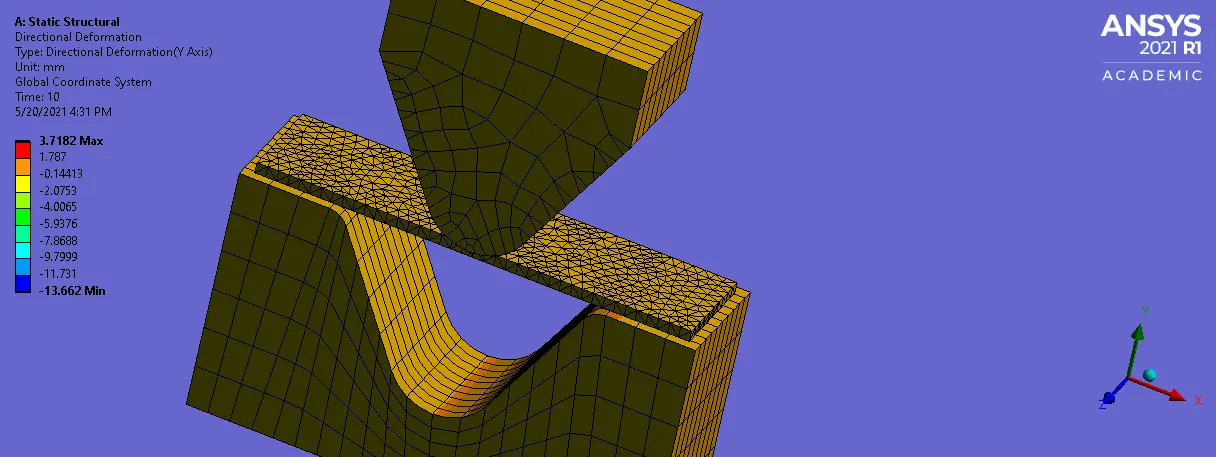
Deformation:
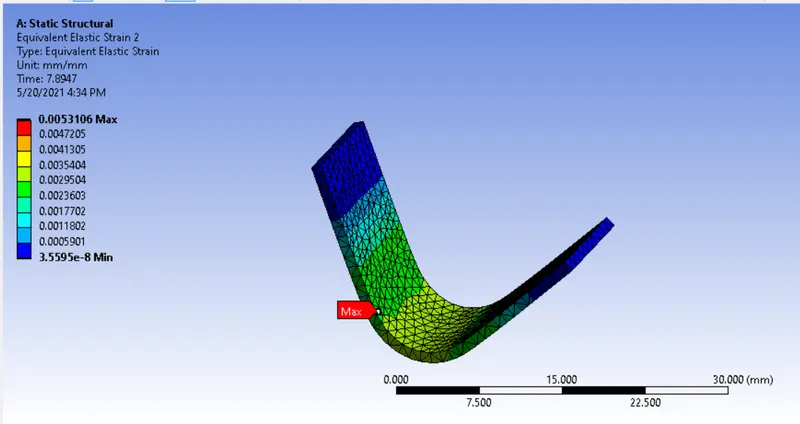
Strain:
- Case 3: Refine the mesh on the plate such that it doesn't cross the academic limit. With Aluminium alloy as material, run the analysis.
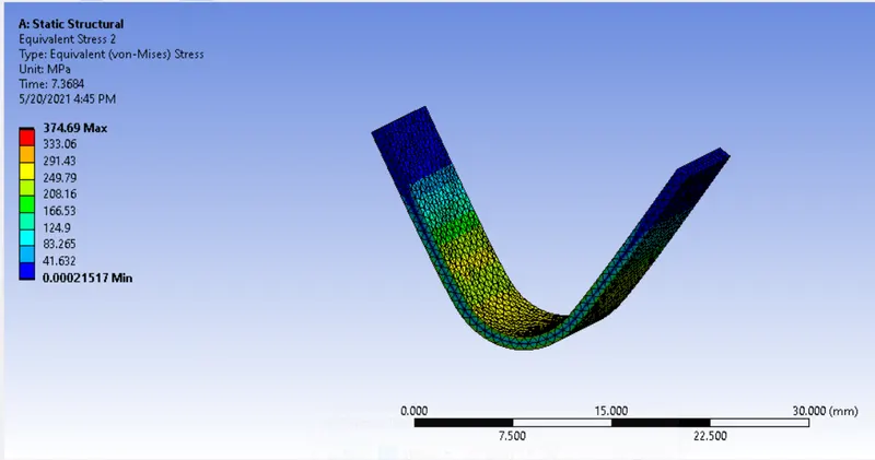
Stress contour:
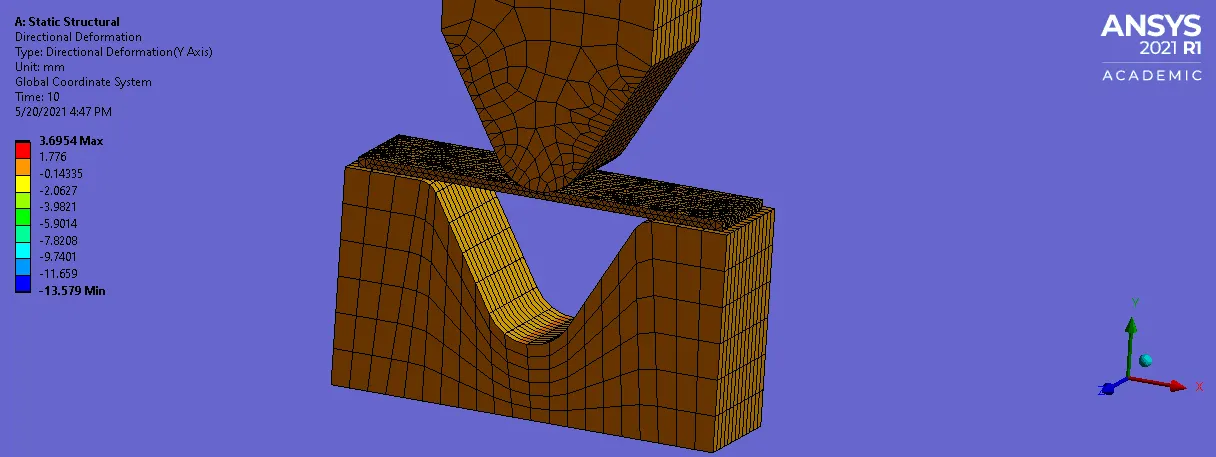
Displacement:
Strain:
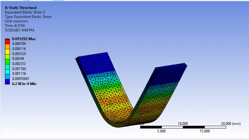
- Comparison of results:

For Case 2 and Case 3 same material is used but with mesh refinement. Also no significant difference in the output result is observed for Case 2 and Case 3. For this case, 1 mm element size can be said
to be optimal element size. Compared to Case 1, aluminium alloy has the highest induced stress after copper alloy followed by Magnesium alloy and Aluminium alloy 1199. This is due to difference in the
properties of the material like Young's modulus, yield strength and tangent modulus.
- Conclusion: Thus, the different cases with different materials are studied and how the material properties affects the output results is observed.